Page 70 of 96
© 2020 LINAK A/S
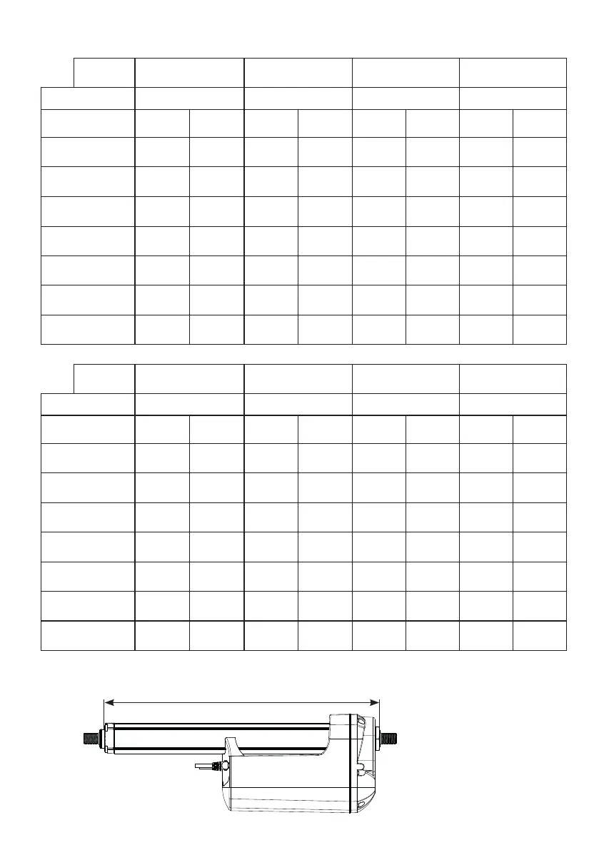
Built-in dimensions
* These built-in dimensions are measured according to the illustration below.
Built-in dimensions
Piston rod “0” /from the surface “1” / to the centre of
the hole
“2A” / to the centre of
the hole
“3” / from the surface
Back fixture Stroke <=300 Stroke > 300 Stroke <=300 Stroke > 300 Stroke <=300 Stroke > 300 Stroke <=300 Stroke > 300
“0” / from the surface 189 239 194 244 194 244 181 231
“1” and “2” / to the
centre of the hole
195 245 200 250 200 250 187 237
“3” and “4” / to the
centre of the hole
195 245 200 250 200 250 187 237
“5” / from the surface 180 230 185 235 185 235 173 223
“6” / from the surface 180 230 185 235 185 235 173 223
“7” and “8” / to the
centre of the hole
195 245 200 250 200 250 187 237
“A” and “B” / to the
centre of the hole
195 245 200 250 200 250 187 237
“C” and “D” / to the
centre of the hole
195 245 200 250 200 250 187 237
Piston rod “4” /from the surface “5” / to the centre of
the hole
“C” / to the centre of
the hole
“D” / to the centre of
the hole
Back fixture Stroke <=300 Stroke > 300 Stroke <=300 Stroke > 300 Stroke <=300 Stroke > 300 Stroke <=300 Stroke > 300
“0” / from the surface 181 231 194 244 209 259 209 259
“1” and “2” / to the
centre of the hole
187 237 200 250 215 265 215 265
“3” and “4” / to the
centre of the hole
187 237 200 250 215 265 215 265
“5” / from the surface 172 222 185 235 200 250 200 250
“6” / from the surface 172* 222* 185 235 200 250 200 250
“7” and “8” / to the
centre of the hole
187 237 200 250 215 265 215 265
“A” and “B” / to the
centre of the hole
187 237 200 250 215 265 215 265
“C” and “D” / to the
centre of the hole
187 237 200 250 215 265 215 265