Page 49 of 96
© 2020 LINAK A/S
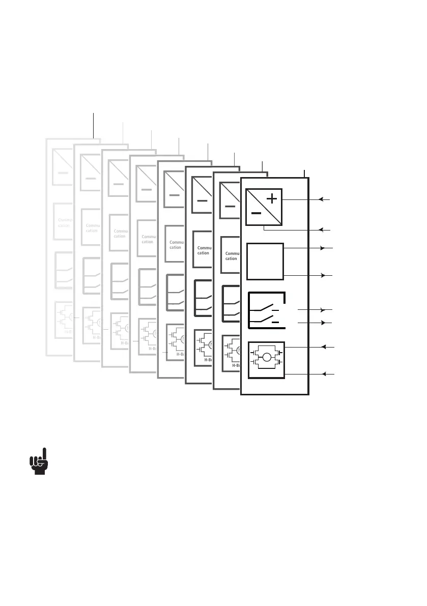
Actuator with Parallel
• Please be aware that if the power supply is not properly connected, you might damage the actuator!
• The green and yellow wires from parallel connected actuators must NOT be interconnected.
(See I/O specifications for endstop on page 18).
Connection diagram:
Fig. 15 : 36xxxxx9xxxxxxx
36xxxxxxxx03xx-xxxxxxxxxxxxxxx
Actuator 1
Actuator 2
Actuator 3
Actuator 4
Actuator 5
Actuator 6
Actuator 7
Actuator 8
INWARDS
OUTWARDS
M
H-Bridge
Communi-
cation
IN
OUT
INWARDS
OUTWARDS
M
H-Bridge
Communi-
cation
IN
OUT
INWARDS
OUTWARDS
M
H-Bridge
Communi-
cation
IN
OUT
INWARDS
OUTWARDS
M
H-Bridge
Communi-
cation
IN
OUT
INWARDS
OUTWARDS
M
H-Bridge
Communi-
cation
IN
OUT
INWARDS
OUTWARDS
M
H-Bridge
Communi-
cation
IN
OUT
INWARDS
OUTWARDS
M
H-Bridge
Communi-
cation
IN
OUT
12/24V DC
BLACK
RED
INWARDS
OUTWARDS
M
H-Bridge
BROWN
Communi-
cation
WHITE
VIOLET
YELLOW
GREEN
IN
OUT
BLUE