Page 50 of 96
© 2020 LINAK A/S
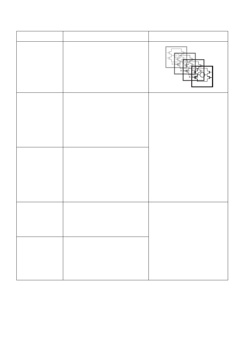
Actuator with Parallel
I/O specifications:
Input/Output Specification Comments
Description Parallel drive of up to 8 actuators. A
master actuator with an integrated
H-bridge controller controls up to 7 slaves.
The version with “IC option” cannot be
operated with PWM (power supply).
See connection diagram,
fig. 15, page 49
Brown 12-24VDC + (VCC)
Connect Brown to positive
12V ± 20%
24V ± 10%
12V, current limit 30A
24V, current limit 20A
Note: Do not change the power supply
polarity on the brown and blue wires!
The parallel actuators can run on one
OR separate power supplies
Power supply GND (-) is electrically
connected to the housing
Current limit levels can be adjusted
through BusLink (only one actuator at
a time for parallel)
If the temperature drops below 0°C,
all current limits will automatically
increase to 30A for 12 V and 25 A for
24 V
Blue 12-24VDC - (GND)
Connect Blue to negative
12V ± 20%
24V ± 10%
12V, current limit 30A
24V, current limit 20A
Red Extends the actuator On/off voltages:
> 67% of V
IN
= ON
< 33% of V
IN
= OFF
Input current: 10mA
It does not matter where the in/out sig-
nals are applied. You can either choose
to connect the signal cable to one
actuator OR you can choose to con-
nect the signal cable to each actuator
on the line. Either way this will ensure
parallel drive
Black Retracts the actuator
M
H-Bridge