Page 44 of 96
© 2020 LINAK A/S
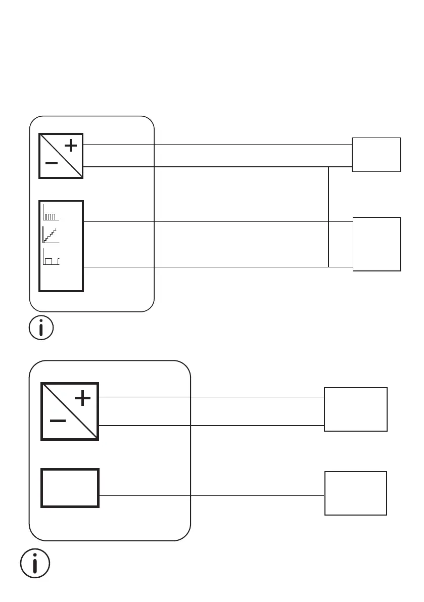
Correct wiring of Power GND and Signal GND for IC Basic and IC Advanced
When using the feedback output, it is important to use the right connection setup. Attention should be paid to
the two ground connections. Power GND in the Power connector and Signal GND in the Control connector. When
using either 0-10V, Hall or PWM feedback, the Signal GND must be used. For optimal accuracy, the Signal GND is
connected to the Power GND as close as possible to the feedback input equipment.
FEEDBACK
SIGNAL GND
50%50%
Hall
0-10V
PWM
4-20mA
Power
supply
Feedback
input
Power connector
Control connector
POWER
POWER GND
WHITE
VIOLET
BROWN
BLUE
50%50%
LA36 IC actuator
Please note that this section only applies for the following feedback options: 0-10V, Hall and PWM.
LA36 IC actuator
FEEDBACK
4-20mA
Power
supply
Feedback
input *
Power connector
Control connector
POWER
POWER GND
VIOLET
BROWN
BLUE
* Only to be used on differential input card. Do not use single ended input card.
Do NOT connect or put the white wire anywhere near GND, as this will create ground loops, disturbing
the mA-signal.
The following connection illustration applies to 4-20mA only: