Page 43 of 96
© 2020 LINAK A/S
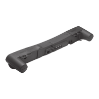
Actuator with IC Advanced - with BusLink
I/O specifications:
Input/Output Specification Comments
Violet Analogue feedback (0-10V):
Configure any high/low combination
between 0-10V
Ripple max. 200mV
Transaction delay 20ms
Linear feedback 0.5%
Max. current output. 1mA
Single Hall output (PNP):
Movement per Single Hall pulse:
LA362C: Actuator = 0.1 mm per count
LA363C: Actuator = 0.2 mm per count
LA363B: Actuator = 0.3 mm per count
LA363A: Actuator = 0.4 mm per count
LA365A: Actuator = 0.7 mm per count
Frequency:
Frequency is 30-125 Hz on Single Hall
output depending on load and spindle.
Overvoltage on the motor can result in
shorter pulses
Output voltage min. V
IN
- 2V
Max. current output: 12mA
Max. 680nF
Open collector source current max. 12mA
Digital output feedback PWM:
Configure any high/low combination
between 0-100%
Output voltage min. V
IN
- 2V Frequency:
75Hz ± 10Hz as standard, but this can
be customised.
Duty cycle: Any low/high combination
between 0 and 100 percent.
Open collector source current max. 12mA
Analogue feedback (4-20mA):
Configure any high/low combination
between 4-20mA
Tolerances ± 0.2mA
Transaction delay 20ms
Linear feedback 0.5%
Output: Source
Serial resistance:
12V max. 300 ohm
24V max. 900 ohm
All absolute value feedbacks (0-10V,
PWM and 4-20mA)
Standby power consumption:
12V, 60mA
24V, 45mA
It is recommendable to have the actuator
to activate its limit switches on a regular
basis, to ensure more precise positioning
White Signal GND For correct wiring of power GND and
Signal GND see page 45
• Current cut-offs should not be used as stop function! This might damage the actuator. Current cut-
offs should only be used in emergencies!
• Current cut-off limits are not proportional with the load curves of the actuator. This means that the
current cut-offs cannot be used as load indicator.
• There are tolerances on the spindle, nut, gear wheels etc. and these tolerances will have an
influence on the current consumption for the specific actuator.