Page 21 of 96
© 2020 LINAK A/S
Actuator with endstop signals and relative positioning - Dual Hall
I/O specifications:
Input/Output Specification Comments
Description The actuator can be equipped with Dual
Hall that gives a relative positioning
feedback signal when the actuator moves.
See connection diagram,
fig. 4, page 21
Brown 12, 24, 36 or 48 VDC (+/-)
12 V ± 20%
24 V ± 10%
36 V ± 10%
48 V ± 10%
Under normal conditions:
12 V, max. 26 A depending on load
24 V, max. 13 A depending on load
36 V, max. 10 A depending on load
48 V, max. 6.5 A depending on load
To extend actuator:
Connect Brown to positive
To retract actuator:
Connect Brown to negative
Blue To extend actuator:
Connect Blue to negative
To retract actuator:
Connect Blue to positive
Red Signal power supply (+)
12-24VDC
Current consumption:
Max. 40mA, also when the actuator is
not running
Black Signal power supply GND (-)
Green Hall B
Movement per single hall pulse:
LA362C Actuator = 0.4 mm per
pulse
LA363C Actuator = 0.7 mm per
pulse
LA363B Actuator = 1.0 mm per
pulse
LA363A Actuator = 1.7 mm per
pulse
LA365A Actuator = 2.9 mm per
pulse
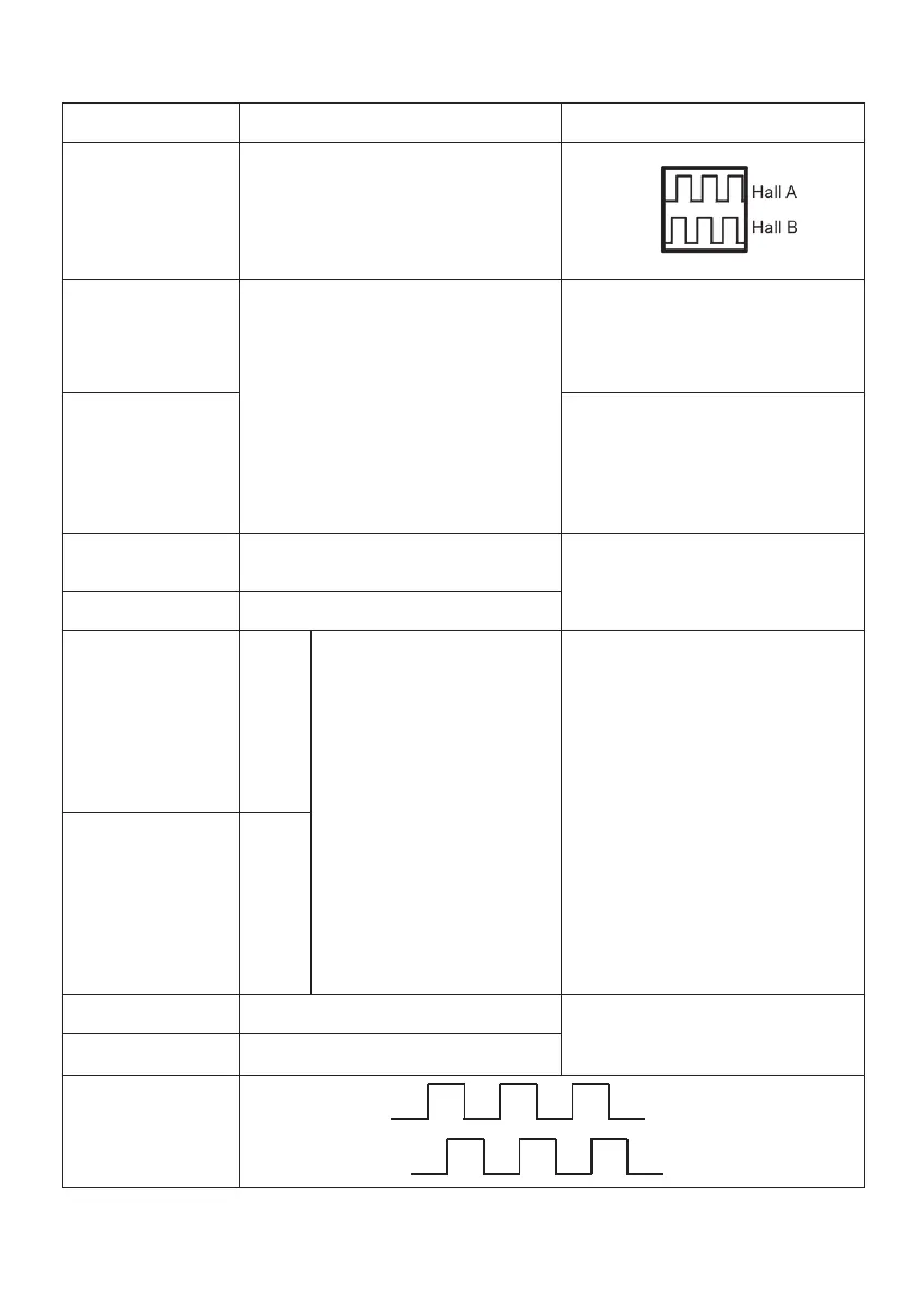
The Hall sensor signals are generated
by the turning of the actuator gearing.
These signals can be fed into a PLC
(Programmable Logic Controller). In the
PLC the quadrature signals can be used
to register the direction and position of
the piston rod.
Output voltage min. V
IN
- 1V
Current output 12mA
Overvoltage on the motor can result in
shorter pulses.
N.B. For more precise measurements,
please contact LINAK A/S.
Yellow Hall A
Violet Endstop signal in Output voltage min. V
IN
- 2V
Source current max. 30mA
NOT potential free
White Endstop signal out
Diagram of Dual Hall:
Hall B
Hall A
Fig. 4.1
 Loading...