Page 23 of 96
© 2020 LINAK A/S
Actuator with relative positioning - Single Hall
I/O specifications:
Input/Output Specification Comments
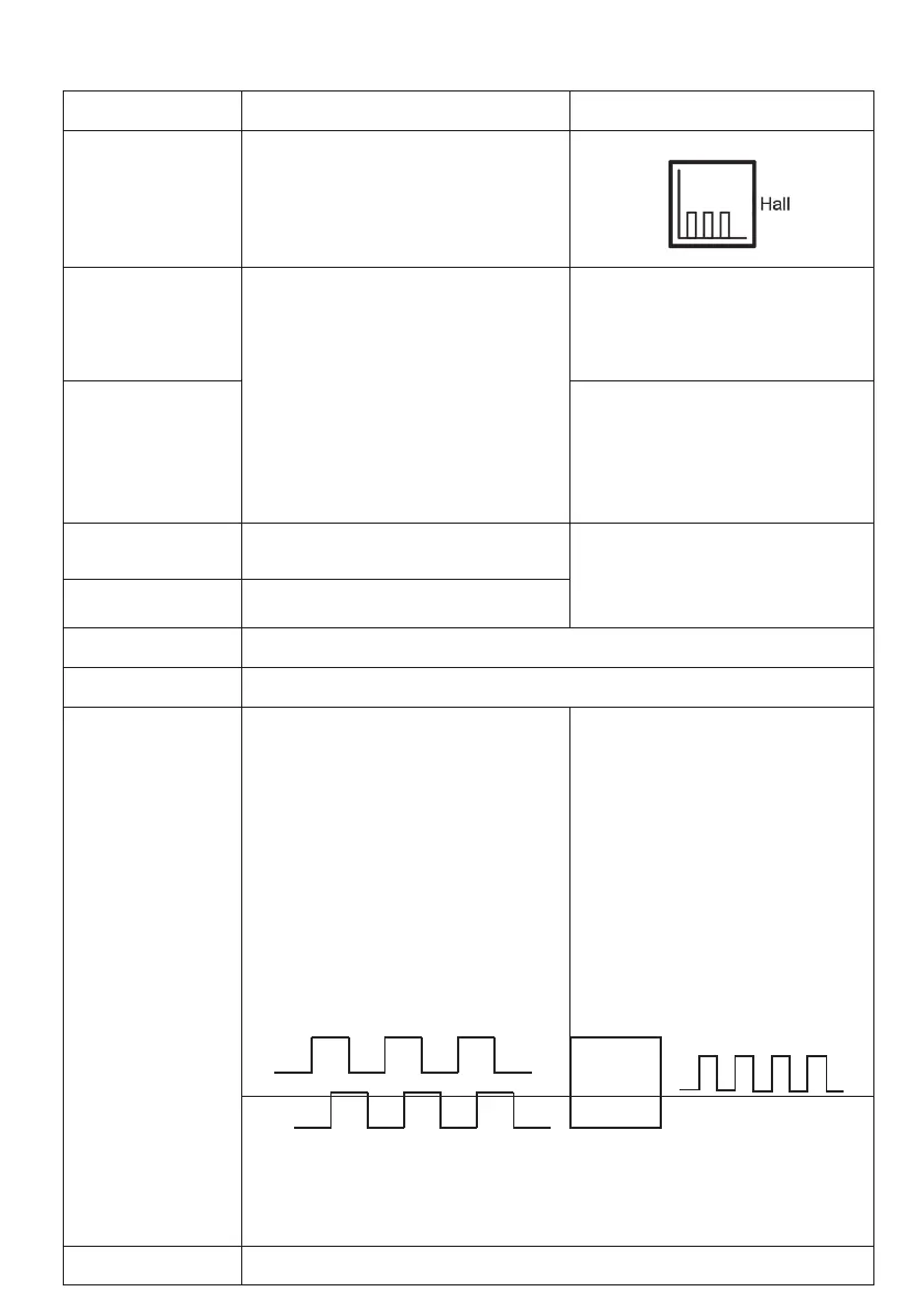
Description The actuator can be equipped with Single Hall
that gives a relative positioning feedback signal
when the actuator moves.
See connection diagram,
fig. 5, page 23
Brown 12, 24, 36 or 48 VDC (+/-)
12 V ± 20%
24 V ± 10%
36 V ± 10%
48 V ± 10%
Under normal conditions:
12 V, max. 26 A depending on load
24 V, max. 13 A depending on load
36 V, max. 10 A depending on load
48 V, max. 6.5 A depending on load
To extend actuator:
Connect Brown to positive
To retract actuator:
Connect Brown to negative
Blue To extend actuator:
Connect Blue to negative
To retract actuator:
Connect Blue to positive
Red Signal power supply (+)
12-24VDC
Current consumption:
Max. 40mA, also when the actuator is not
running
Black Signal power supply GND (-)
Green Not to be connected
Yellow Not to be connected
Violet Single Hall output (PNP)
Movement per Single Hall pulse:
Movement per hall pulse:
Number: Gear
Letter: Pitch
2C = 0.111 mm
3C = 0.166 mm
3B = 0.254 mm
3A = 0.433 mm
5A = 0.721 mm
Frequency:
Frequency is 30-125 Hz on Single Hall output
depending on load and spindle. Overvoltage on
the motor can result in shorter pulses.
Output voltage min. V
IN
- 2V
Max. current output: 12mA
Max. 680nF
N.B. For more precise measurements, please
contact
LINAK A/S.
Low frequency with a high load.Higher fre-
quency with no load.
Diagram of Single Hall:
White Not to be connected
Fig. 5.1
Micro -
Processor
Input Single Hall output
Hall B
Hall A