Page 33 of 96
© 2020 LINAK A/S
Actuator with endstop signals and absolute positioning -
Mechanical potentiometer feedback
I/O specifications:
Input/Output Specification Comments
Description The actuator can be equipped with a
mechanical potentiometer, 10 kohm.
See connection diagram,
fig. 10, page 33
Bourns 0-10 kohm, 5%, 10-Turn
Type: 3540 Wirewound
Brown 12, 24, 36 or 48 VDC (+/-)
12 V ± 20%
24 V ± 10%
36 V ± 10%
48 V ± 10%
Under normal conditions:
12 V, max. 26 A depending on load
24 V, max. 13 A depending on load
36 V, max. 10 A depending on load
48 V, max. 6.5 A depending on load
To extend actuator:
Connect Brown to positive
To retract actuator:
Connect Brown to negative
Blue To extend actuator:
Connect Blue to negative
To retract actuator:
Connect Blue to positive
Red Signal power supply (+)
12-24VDC
For endstop signals
Black Signal power supply GND (-)
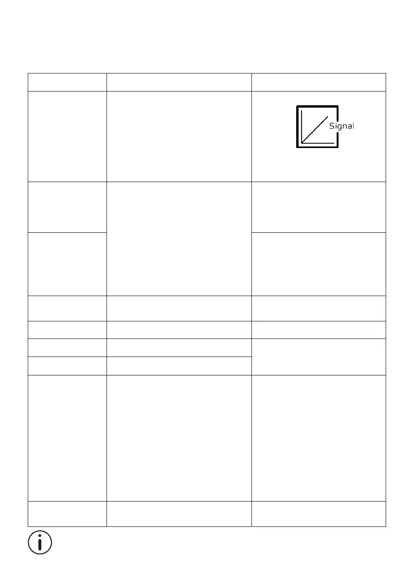
Green Endstop signal out Output voltage min. V
IN
- 2V
Source current max. 100mA
NOT potential free
Yellow Endstop signal in
Violet Mechanical potentiometer output
Output range with 8mm spindle pitch:
0 kohm = 0mm stroke
10 kohm = 333mm stroke
Output range with 12mm spindle pitch:
0 kohm = 0mm stroke
10 kohm = 500mm stroke
Output range with 20mm spindle pitch:
0 kohm = 0mm stroke
10 kohm = 833mm stroke
+10V or other value
Output protection:
1 kohm protection resistor
Linearity: ± 0.25%
White VCC+ to POT
10VDC or other values
Please note that Potentiometer is not possible on variants with fast gear (Spindle pitch 20mm, H Gear).