Page 58 of 96
© 2020 LINAK A/S
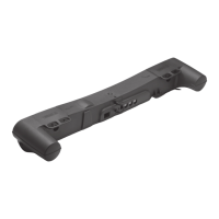
Actuator with CAN bus
I/O specifications:
Input/Output Specification Comments
Description
Compatible with the SAE J1939 standard.
Uses CAN messages to command move-
ment, setting parameters and to deliver
feedback from the actuator.
See the LINAK CAN bus user manual.
Actuator identification is provided, using
standard J1939 address claim or fixed
addresses.
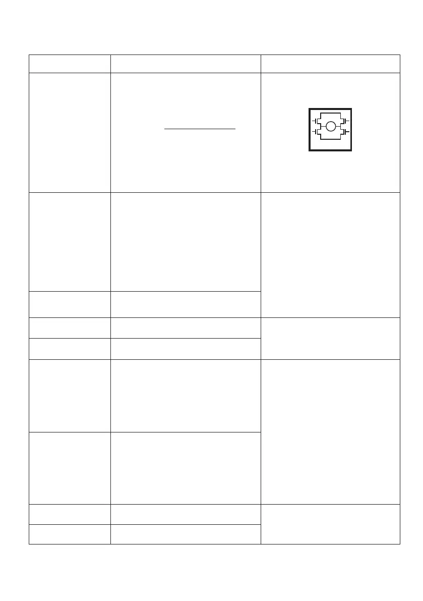
See connection diagram,
fig. 16, page 57
Brown 12-24VDC + (VCC)
Connect Brown to positive
12V ± 20%
24V ± 10%
48 ± 10%
12V, current limit 30A
24V, current limit 20A
48V, current limit 10 A
Note: Do not swap the power supply
polarity on the brown and blue wires!
Power supply GND (-) is electrically
connected to the housing
Current limit levels can be adjusted
through BusLink
If the temperature drops below 0°C,
all current limits will automatically
increase to 30A
Blue 12-24VDC - (GND)
Connect Blue to negative
Red Extends the actuator On/off voltages:
> 67% of V
IN
= ON
< 33% of V
IN
= OFF
Black Retracts the actuator
Green CAN_L LA36 with CAN bus does not contain
the 120Ω terminal resistor. The physical
layer is in accordance with J1939-15. *
Speed: Autobaud up to 500 kbps
(Prototypes: 250 kbps)
Max bus length: 40 meters
Max stub length: 3 meters
Max node count: 10 (can be extended
to 30 under certain circumstances)
Wiring: Unshielded twisted pair
Cable impedance: 120 Ω (±10%)
Yellow CAN_H
Violet Service interface
Only BusLink can be used as service
interface. Use green adapter cable
White Service interface GND
M
H-Bridge
* J1939-15 refers to Twisted Pair and Shielded cables. The standard/default cables delivered with LA36 CAN do not
comply with this.