Recorder Overview3
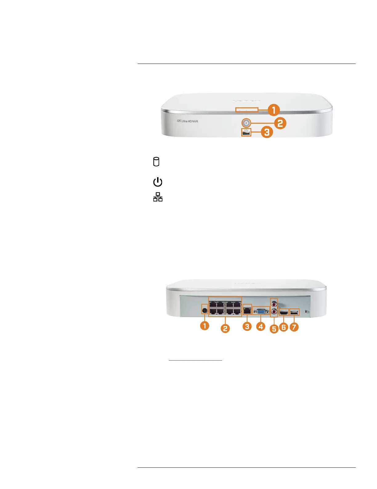
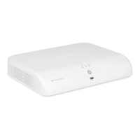
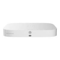
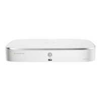
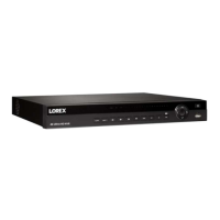
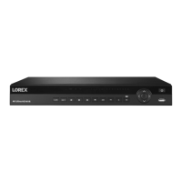
3.1 Front Panel
1. LED Indicators:
•
HDD: Glows to indicate hard drive is operating properly. Turns off when there is a hard
drive error.
•
POWER: Glows to indicate the system is on.
•
NETWORK: Glows to indicate the recorder is connected to the Internet for remote
access and automatic firmware updates. Turns off when there is no Internet access.
2. Info / Panic Button:
• From live view, press once to open the System Information screen.
• Press and hold for 3 seconds to activate the warning lights and sirens on all connected de-
terrence cameras.
3. USB Port: Connect a USB mouse (included) to control the system, or a USB flash drive (not
included) for data backup or manual firmware updates.
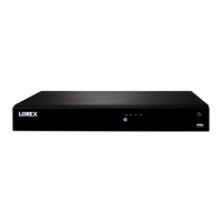
3.2 Back Panel
1. DC 12V: Connect the included power adapter.
2. PoE Video Inputs: Connect Lorex IP cameras to the system. For a full list of compatible cam-
eras, visit lorex.com/compatibility.
3. LAN: Connect the included RJ45 Ethernet cable from the recorder to your router for remote
connectivity and automatic firmware updates.
4. VGA: Connect a VGA monitor (not included) to view the system interface.
5. AUDIO IN/OUT:
• Connect an external microphone to the AUDIO IN port for single-channel audio recording.
• Connect an external speaker to the AUDIO OUT port to hear system audio
• For full details on connecting external audio devices, see 20 Connecting Audio Devices,
page 104.
6. HDMI: Connect to an HDMI monitor or TV (not included) using the included HDMI cable to
view the system interface.
#LX400113; r. 1.0/56015/56022; en-US 5