Chapter 2 System Configuration
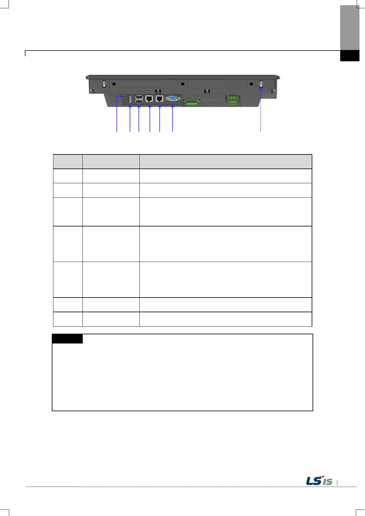
No. Name Function
12
Audio-Out Stereo audio output
13
HDMI Clone mode display output
14
USB host
1) USB memory connection: Logging / Recipe / Alarm / Project data
Backup and transfer
2) User Interface Connection: Use mouse / Keyboard
3) Printer connection: Print function
15
Ethernet terminal
Ethernet: 10Base-T / 100Base-TX
1) Project data transmission
2) Logging / Recipe / Alarm / Screen Data Backup
3) Upgrading the device software
4) PLC / control device communication
16 Ethernet terminal
Ethernet: 10Base-T / 100Base-TX / 1000Base-T
1) Project data transmission
2) Logging / Recipe / Alarm / Screen Data Backup
3) Upgrading the device software
4) PLC / control device communication
17
RS-232C connector RS-232C (COM2): PLC / Control device communication
18
Anti-drop lock
Thanks to anti-drop lock, the Panel can be installed in a panel by a single
operator.
(1) The surface of the touch panel must be kept clean at all times.
- Foreign objects (water, oil, etc.) on the touch panel may cause malfunction.
(2) Touching the front of the touch panel may cause malfunction.
- Be careful that conductive objects do not touch the touch panel.
(3) The switch No. 1/2 of the setting switch must be set in the same direction.
- If switches 1 and 2 are set in different directions, communication problems may occur.
(4) Refer to the communication manual for details on communication connection.
(5) Please refer to Chapter 10 for installation details.
 Loading...