Lucent Technologies Galaxy Power System 4848/100
11 - 8 Maintenance and Replacement Issue 5 June 2000
Replacement Procedures, continued
Replacing the
Rectifier Fan
Assemblies
Replacing the Rectifier Fan Assemblies
Step Action
1
Follow instructions in the “Removing a Rectifier” procedure
in this section. Refer to Figure 11-1.
2
Place rectifier on a flat surface at a comfortable working
height.
3
Loosen the front cover (white) by removing 14 screws (5 top,
5 bottom, 2 on each side). Before fully removing the cover,
disconnect the ribbon cable from the display circuit pack.
Caution
Allow the front end of the rectifier to overhang the
working surface. To remove bottom screws, turn the
rectifier on its side, or work below the table surface.
Never tilt the front of the unit to gain access to the bottom
screws. This will result in damage to the rear connector.
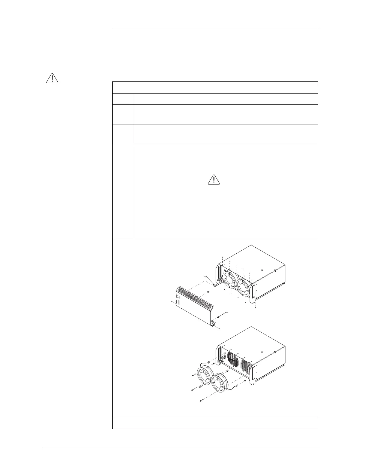
Figure 11-2: Replacing a Rectifier Fan Assembly
Continued on next page.
Ribbon Cable
To Display
All Screws Shown Except for
Fan Mounting Screws Below
#6-32 x 5/16" (846743656)
Torque to 10 in-lbs (1.1 Nm)
Fan Mounting Screws
#6-32 x 2 1/4" (846427839)
Torque to 10 in-lbs (1.1 Nm)
Fans
(847755378)
Rotron, PQ48 Box-031868
Threaded Taper Pin
Torque to 10 in-lbs (1.1 Nm)