Lucent Technologies Galaxy Power System 4848/100
Issue 5 June 2000 System Description 2 - 1
2 System Description
Overview
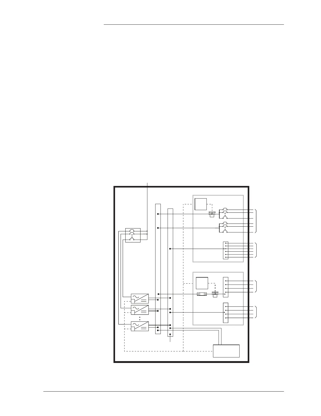
Block Diagram Figure 2-1 shows a basic block diagram of the Galaxy Power System
4848/100. It illustrates the arrangement and interconnections of the
system components from the ac input to the dc output.
Figure 2-1: Block Diagram of the GPS 4848/100
LVLD
DISCHG RTN
LVLD
Control
Board
Rectifiers
DC Distribution
Controller
Return
Bus
(+)
To 48 Volt
Loads
AC Input
Power
48V
Returns
LVBD
BAT BUS
CHG RTN
LVBD
Control
Board
Battery Distribution
Battery (-)
Battery
Shunt
Battery (+)
CO
GND
Sense/Control
Connections
AC Input
Chg
Bus
(-)