Lucent Technologies Galaxy Power System 4848/100
11 - 10 Maintenance and Replacement Issue 5 June 2000
Testing Note: Consult the Installation Guide for Galaxy Power Systems (Select
Code 167-792-157) for complete testing guidelines for new
installations.
Testing Additional
Alarms After
Replacing
Rectifiers
Alarm operation may be verified while the system operates at float
voltage.
Testing Rectifiers
and Load Share in
Bay Expansions
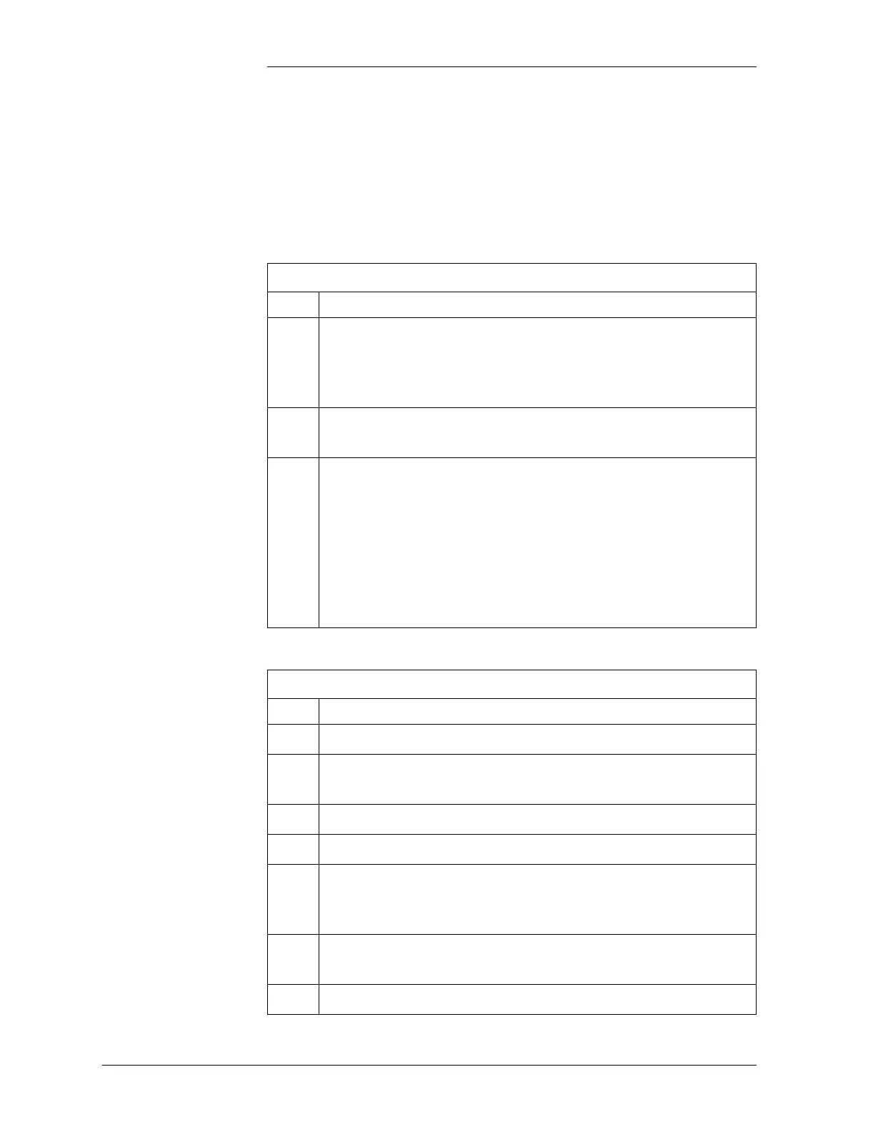
Testing Additional Alarms After Replacing Rectifiers
Step Action
1
Turn OFF the ac circuit breaker of replaced rectifier. Verify
that the AC and MIN alarm LEDs illuminate, the rectifier
displays ACF, and the controller alarms screen indicates
RECTIFIER FAIL : Gmm (SCF and Millennium controllers).
2
Turn ON the ac circuit breaker of the replaced rectifier. Verify
that the rectifier starts and the alarms retire.
3
OPTIONAL: Simulate a load circuit breaker alarm by
shorting the alarm contacts on the circuit breakers or inserting
an operated alarm fuse. For ED83143-30 G1-6 (101-106),
add a jumper from the hot bus to the FAJ input signal on the
associated BNL1 (P4-1) or BNL7 (P5-6) alarm card. Verify
that the DIST and MAJ alarm LEDs illuminate and the
controller alarms screen indicates EXTERNAL FUSE
MAJOR (SCF and Millennium controllers).
Testing Rectifiers and Load Share in Bay Extensions
Step Action
1
Turn all rectifiers to STBY.
2
Connect a resistive load box (proper voltage) to the system’s
positive and negative bus bars.
3
Verify that the system load is less than 50 amperes.
4
Increase the system load to 200 amperes.
5
Turn ON all the rectifiers; after approximately 60 seconds,
verify that the load is divided equally among all the rectifiers
(within 2 amperes).
6
Reduce the system load. Verify that the rectifiers continue to
share the load.
7
Remove system load.