Lynx NGT-9000
Installation Manual
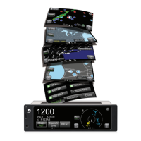
Figure 3-2: Maintenance Application Tool – Main Page
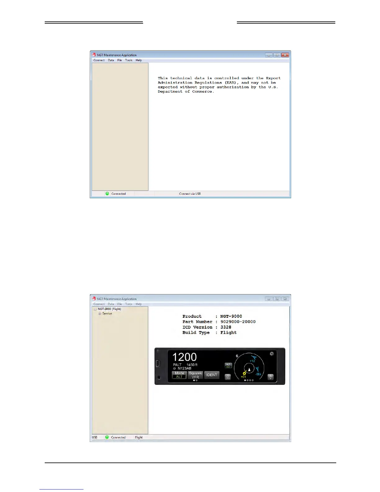
d. Communication is established when the Lynx MAT left view panel changes from grey to tan
and the message “Connected” is shown in the lower communication bar. See Figure 3-3.
• If “Not Connected – red indicator” is shown, then check the USB cable for proper
connection.
• If a “Response timeout for write request” message is seen on the status bar, then the unit is
not responding to requests. Cycle power to the unit.
• When the unit is in maintenance mode the ADS-B Out Fail lamp is ON (if installed).
Figure 3-3: Lynx MAT – Main Screen
Page 3-4 Installation Checkout 0040-17001-01
January 15, 2015 Revision A
 Loading...