215626 35 Revision A
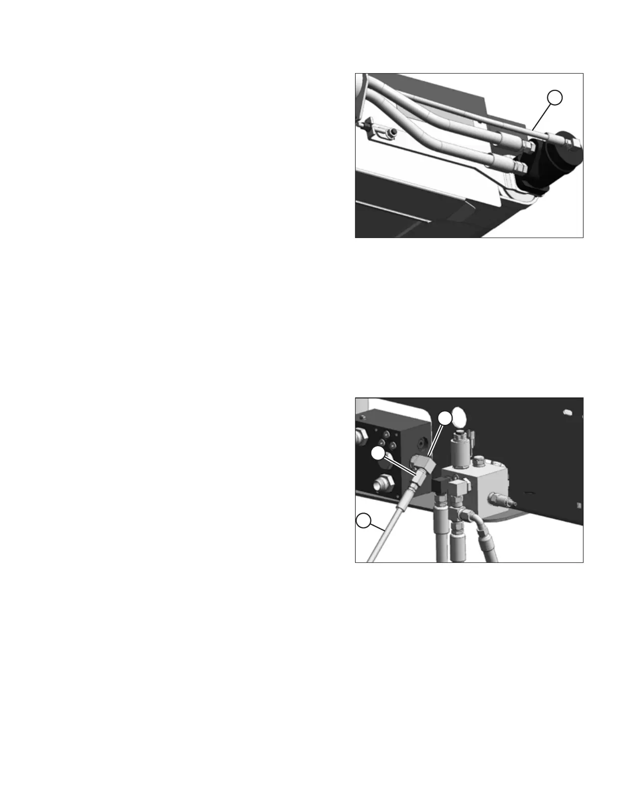
Figure 2.58: Case Drain Hose
To install case drain hose (A), proceed to the section that
applies to your windrower/header configuration:
• M150/M200 and A Series without reverser. Refer to 2.6.1
Installing Case Drain Hose – M150/M200 and A Series
Headers without Reverser, page 35.
• M150/M200 and A Series with reverser. Refer to 2.6.2
Installing Case Drain Hose – M150/M200 and A Series
Headers with Reverser, page 36.
• M150/M200 and D Series without reverser. Refer to 2.6.3
Installing Case Drain Hose – M150/M200 and D Series
Headers without Reverser, page 37.
• M150/M200 and D Series with reverser. Refer to 2.6.4
Installing Case Drain Hose – M150/M200 and D Series
Headers with Reverser, page 38.
• M150/M200 and R Series. Refer to 2.6.5 Installing Case Drain Hose – M150/M200 and R Series Headers, page 38.
• M155/M155E4/M205, all header types. Refer to 2.6.6 Installing Case Drain Hose – M155/M155E4/M205 with All
Headers, page 39.
2.6.1 Installing Case Drain Hose – M150/M200 and A Series Headers without
Reverser
The case drain hose must be connected to the header drive block on M150/M200 windrowers using A Series headers
without reversers.
Figure 2.59: Header Drive Block
1. Connect #12 ORB x #10 JIC elbow (B) to port T on the
header drive block.
2. Connect #10 JIC x #6 JIC reducer (C) to elbow (B).
3. Attach case drain hose (A) to reducer (C).
NOTE:
Make sure that hose (A) is not rubbing against any fittings.
Refer to 5.5 Hydraulics and In-Cab Electrical, page 98 for
additional information on the hydraulic connections.
4. Proceed to 2.7 Installing Auxiliary Valve Block, page 40.
SETUP INSTRUCTIONS