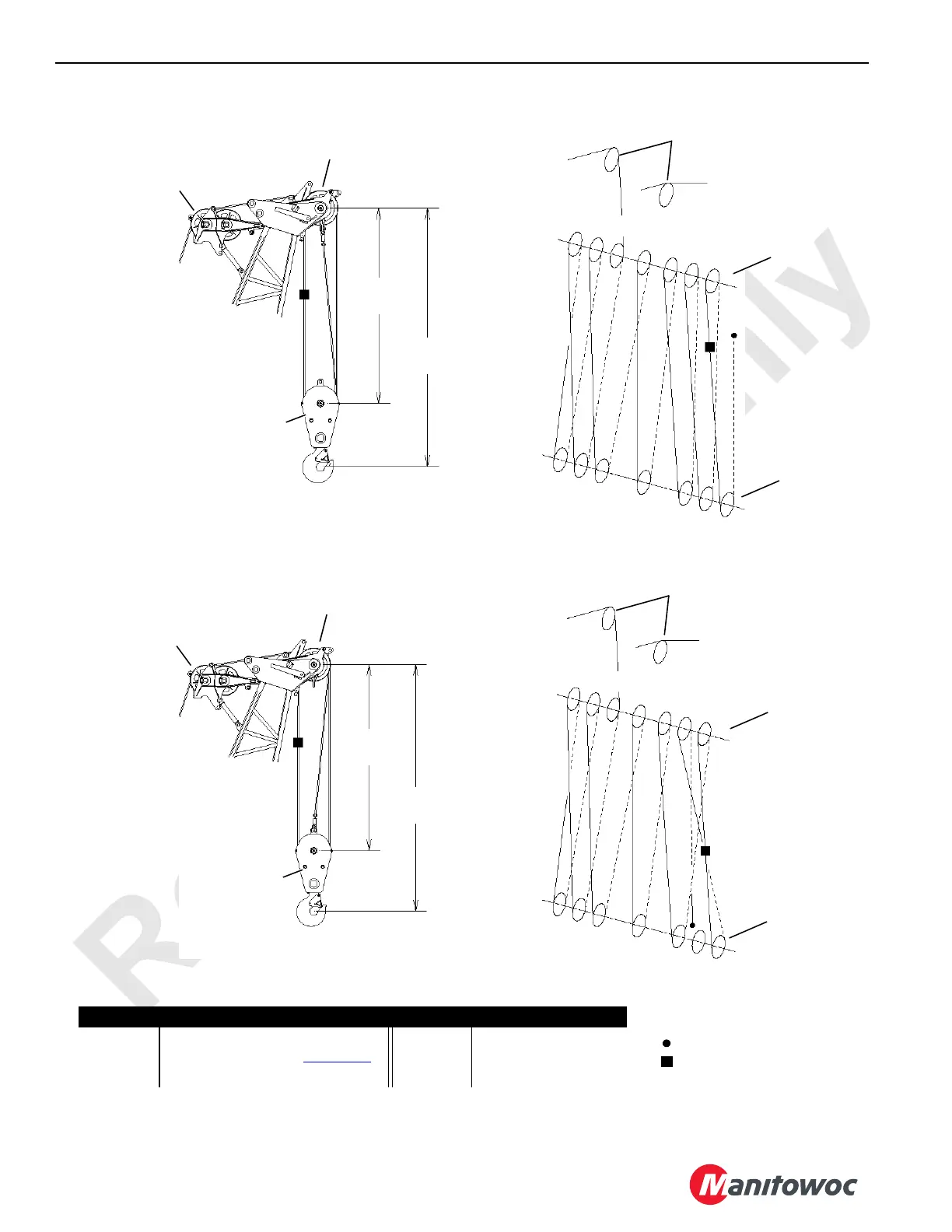
FIGURE 4-57
R
F
2
1
3
S7
S6
S5
S4
S3
S2
S1
2
3
1
R
F
2
1
3
S7
S6 S5
S4
S3
S2
S1
2
3
1
Item Description Item Description
1 Boom Top Wire Rope Guide F Front Drum (Drum 1)
2 Upper Boom Point (see Figure 4-56
) R Rear Drum (Drum 2)
3 Load Block — 220 USt (199,6 t)
6064-1_2
14.0 ft
4,3 m
18.6 ft
5,7 m
14.0 ft
4,3 m
18.6 ft
5,7 m
NOTE: Load block (3) to Lower Boom Point
(2) minimum distance is controlled
by 2-1/2° fleet angle
14 Parts of Line
13 Parts of Line
Dead-End Socket And Wedge
Block-Up Limit Weight

 Loading...


