Grove Published 7-23-2020, Control # 668-02 4-109
GRT9165 OPERATOR MANUAL OPERATING PROCEDURES
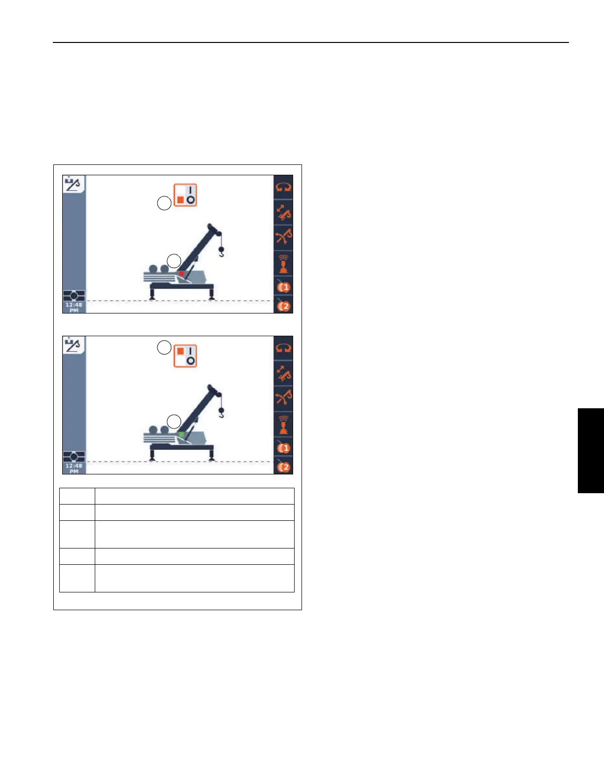
The Boom Removal/Installation function screen
(Figure 4-114) is used to enable the hydraulic system that
operates the pin-puller mechanism. The pin-puller is used to
remove/install the boom pivot pins.
Before setting the Boom Removal/Installation function to On
and enabling the system, make sure the Pin Pull mechanism
is installed at the boom pivot pins and the hydraulic
connections are made.
To enable the Pin Pull system, use the Jog Dial or Arrow
Buttons at the Navigation Control Pad to select the On icon
(3, Figure 4-114). Press the Jog Dial or the OK Button to set
the system to On. The Pin Pull Status indicator shows green
(4, Figure 4-114) to indicate the system is enabled.
To disable the Pin Pull system, use the Jog Dial or Arrow
Buttons to select the Off icon (1, Figure 4-114). Press the
Jog Dial or the OK Button to set the system to Off. The Pin
Pull Status indicator shows red (2, Figure 4-114) to indicate
the system is disabled.
Complete procedures for the removal and installation of the
boom, including the use of the Pin Pull mechanisms, are
found in the Service Manual.
FIGURE 4-114
9902-18
3
9902-19
1
2
4
Item Description
1 Off Icon
2
Pin Pull Status Indicator (red - pin-pull system
disabled)
3 On Icon
4
Pin Pull Status Indicator (green - pin-pull
system enabled)

 Loading...


