Grove Published 7-23-2020, Control # 668-02 5-55
GRT9165 OPERATOR MANUAL SET-UP AND INSTALLATION
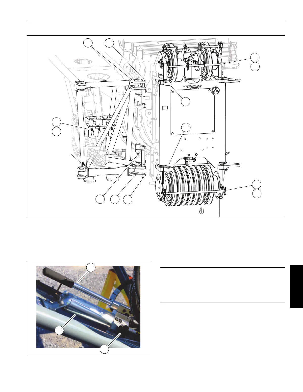
10. Remove pins (5, Figure 5-40) and retaining clips (6) from
the stowage bracket. Secure the boom extension to the
boom nose using four pins (5). Secure the pins (5) with
retaining clips (6). If necessary, remove the upper (7)
and lower (8) hoist rope rods and retaining clips (9) to
install the pins (5). Use the jack as necessary to install
the fourth pin as necessary as follows:
a. Install three pins to attach the boom extension to the
boom nose.
b. Operate the jack handle (2) to align the holes on the
boom extension with the hole in the boom nose.
c. Install the fourth pin. Secure the fourth pin with
retaining clip.
d. Turn the nob (3) to relieve the pressure to retract the
jack pin.
11. Connect boom extension electrical connector to the
main boom electrical connector. For more information,
see Boom Extension and Lattice Insert Electrical
Connections, page 5-72.
2
2
3
1
4
4
1
6
5
7
9
8
9
9987
FIGURE 5-40
CAUTION
After installing the fourth pin, turn the pressure relief nob
(3) to retract the jack so the jack does not contact the
boom nose. Failure to retract the jack could result in
damage to the boom extension jack.

 Loading...


