Grove Published 7-23-2020, Control # 668-02 5-71
GRT9165 OPERATOR MANUAL SET-UP AND INSTALLATION
boom extension offset as needed to align the
arrows. For more information, see Setting the
(Optional) Hydraulic Boom Extension Offset, page
5-79.
8. Stow the rear mast assembly as follows:
a. Hold the handle (1, Figure 5-57) and remove the
retaining clip (2) and pin (3).
b. Lower the mast (4). Make sure the connecting point
holes are aligned.
c. Insert pin (3). Secure the pin with retaining clip (2).
9. Stow the front mast assembly as follows:
a. Hold the handle (1, Figure 5-58) of the mast sheave
assembly. Remove retaining clip (3) and pin (4).
b. Lower the mast assembly (2) until the connecting
holes are aligned.
c. Insert pin (4) and secure with retaining clip (3).
10. Attach a tag line (1, Figure 5-37) to the end of the boom
extension base section (2).
11. Make sure the boom extension installation pins (4,
Figure 5-40) are engaged.
12. Remove the four pins (5, Figure 5-40) and retaining clips
(6) that attach the boom extension base section to the
boom nose. If necessary, remove the upper (7) and
lower (8) hoist rope rods and retaining clips (9) to install
the pins (5). Store the pins (5) and retaining clips (6) on
the boom extension stowage bracket.
13. Swing the boom extension to the intermediate position
on the side of the base section of the boom. Make sure
the wheels engage on the front and rear boom extension
ramps.
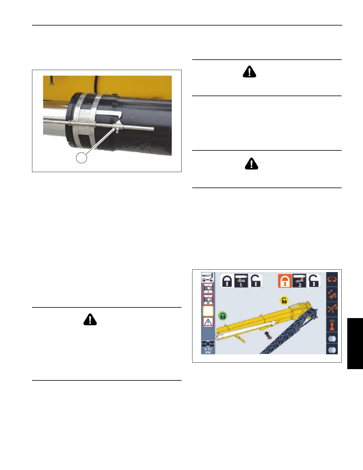
14. From the operator cab, lock the front mounting pin (Pin
#2 in the ODM) as follows:
a. Use the ODM navigation pad arrow buttons or jog
dial to highlight the Pin #2 lock icon.
The lock icon is highlighted (orange).
b. Press and hold the OK on the ODM navigation pad
or press down on the jog dial.
When front extension pin is locked, the status
indicator show a green lock icon.
DANGER
Boom Extension Hazard!
The boom extension installation pins (4, Figure 5-40)
must be extended and engaged before removing the four
pins (5, Figure 5-40). If the boom extension installation
pins (4, Figure 5-40) are not extended and fully engaged,
the boom extension will fall when pins (5, Figure 5-40) are
removed, resulting in possible injury or death.
CAUTION
After removing the four retaining clips and pins, the boom
extension is free to swing to the side of the main boom.
DANGER
When erecting the boom extension, make sure that all
personnel and equipment are kept clear of the swing path.

 Loading...


