National Crane Published 08/16/19 Control # 112-05 9-27
500E2 SERVICE MANUAL CRANE INSTALLATION
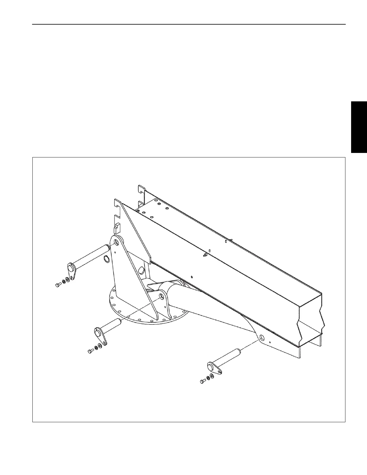
BOOM INSTALLATION
Lift Cylinder Installation
NOTE: Before attempting to assemble the boom and lift
cylinder to the frame, see
Pin Bearing Inspection
and Installation
pages in this section. Before
connecting hoses, boom must be opposite (180°)
the rotation stop to minimize hose twist.
1. Pin lift cylinder barrel in position in the turret.
2. Pin boom pivot to turret. (It will be necessary to use an
overhead hoist for lifting boom and lift cylinder.)
3. Connect the 1/2 inch R12 hoses to the lift cylinder.
4. Support outer end of boom securely and use the
overhead hoist to position the lift cylinder with the control
valve to pin the cylinder to the boom ears. Torque pin
keeper capscrews to proper torque.
5. Grease the three pin joints with gun grease and operate
the boom and lift cylinder through several complete
cycles before placing machine in operation.
6. Route the 1/2 inch R12 telescope hoses over the turret
back plate and to the back side of the boom. Connect
the telescope cylinder connections at the back of the
boom.
7. Route the 3/4 inch R12 hoist hoses and the 1/4 inch R1
hoist drain hose through the turret then through the
holes in the side of the hoist side plates and connect to
the hoist fittings.

 Loading...


