National Crane Published 08/16/19 Control # 112-05 9-37
500E2 SERVICE MANUAL CRANE INSTALLATION
INITIAL CRANE RUN IN PROCEDURE
1. Engage the PTO and run the truck engine at idle to
activate the pump (approximately 600 rpm). Turn the
crane power switch on and operate the crane and
outriggers though all of their functions at least six (6)
times to purge cylinders of air. Operate the control
valves slowly with the truck engine at idle and cycle each
cylinder through its complete stroke each time. Check to
see that movement of outriggers and boom correspond
with direction indicated on switches and levers. Refer to
hydraulic or electrical schematic and parts pages to
correct any problems.
NOTE: Add oil to reservoir as required to keep air from
reentering the system.
2. Set throttle according to engine RPM and PTO ratio to
get 2400 RPM pump shaft speed.
3. When all cylinders have operated through complete
cycles, stow crane and place the outriggers in the up
position. The oil level should be visible near the top of
the sight gage. Lift and stability test must now be
performed on the unit. Hoist and crane tests should be
conducted to insure proper performance.
4. After testing is completed, all cable clamp bolts should
be re-torqued to specifications. Inspect the T-box and
frame mounting bolts for proper tension.
5. Upon completion, overall height of crane vehicle
combination must be measured and posted inside of cab
informing driver of overall height.
STABILITY CHECK
The chassis weight, before the crane is mounted, is intended
for use only as a guideline in determining the total weight
required for the unit to be stable with an 85% tipping factor
(i.e. when lifting capacity load, the unit is at 85% of tipping or
less).
In order to ensure the stability of the unit with an 85% tipping
factor, a live load stability test must be performed on each
completed unit. Proceed as follows:
1. Test the unit for stability on a firm level surface.
2. A Series 500E2 Service Manual crane requires rear
stabilizers for stability. With the boom stowed, set the
unit up level on the outriggers and stabilizers.
3. When stability testing this unit, select the load from the
capacity chart that is listed at the longest boom
extension and approximately 30° of boom elevation.
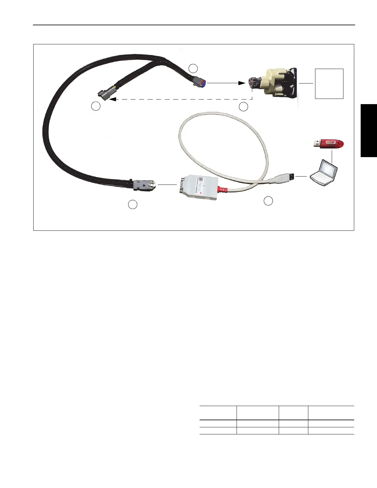
Diagnostics Cable
CAN to USB
Adapter Cable
OMS
Module
Laptop
FIGURE 9-4
Install terminating
resistor.
Remove terminating
resistor from splitter.
1
2
Connect cable.
3
Install serial end of
diagnostics cable to CAN
to USB adapter cable.
4
Connect USB
to laptop.
5
9832
9833
9836
Software
Key
9835
Model
Boom
Length
Loaded
Angle
Loaded
Radius
560E2 60' (18.28 m) 34.5° 50' (15.24 m)
571E2 71' (21.64 m) 32° 60' (18.29 m)

 Loading...


