3-4 Published 08/16/19 Control # 112-05
ELECTRIC SYSTEM 500E2 SERVICE MANUAL
20. Visually inspect interior routing of anti-two-block wire for
excess slack in wire, inaccurate routing of wire, etc.
Correct any problems before boom operation.
HYDRAULIC CAPACITY ALERT SYSTEM
This hydraulic capacity alert system uses the work port
unloader solenoids in the anti-two-block system as the
hydraulic system dump circuit.
The hydraulic capacity alert system has an override switch
and button located on the operator’s console that
momentarily overrides the hydraulic capacity alert and anti-
two-block systems and restores power to crane functions.
When trip pressure is reached, the pressure sensing switch
breaks electrical continuity to the work port unloader
solenoid in the main control valve.When power is removed
from this solenoid, the unloader valves allow the oil flowing to
hoist up, telescope out and boom down to flow to tank. This
path to tank will prevent further operation of these functions.
When the overload condition is corrected by hoisting down,
retracting the boom, or raising the boom, the pressure
sensing switch allows the work port unloader solenoids to be
powered thereby allowing the crane to function normally.
HCA Maintenance & Repair
The following step-by-step analysis will be helpful in isolating
and correcting almost every service problem if followed in a
step-by-step systematic manner. Use this information with
the Hydraulic Schematic and the Illustrated Parts Catalog to
identify parts and follow flow paths. Start at top box and work
downward step by step. Do not try to start in the middle or
skip steps.
1. Refer to Hydraulic Schematic and System Description to
gain a thorough understanding of the capacity alert
system before proceeding with any maintenance.
2. System adjustment must be checked every three
months for accuracy. Refer to the preceding section on
System Adjustment.
3. Always be sure the boom is adequately supported and
no hydraulic pressure remains in the lines before the
pilot pressure line fittings are loosened.
HCA System Adjustment
The hydraulic capacity alert system should be checked for
proper adjustment during initial crane start-up and quarterly
thereafter. The procedure for proper adjustment should be
performed as follows:
NOTE: Trapped air must be bled from the system before
adjustments are made.
1. Remove the console cover on the operators console.
.
2. Start the truck and set the crane up for operation as
prescribed in the Operators Manual.
3. Select a test weight that is equal to crane capacity at an
intermediate boom length and radius.
4. Work with loads which have loaded boom angles near
30°. Starting with the boom at the chosen reference
angle and a radius less than the chosen radius, pick the
weight up with the hoist and begin extending the boom.
5. As the boom is extending, lower the load with the hoist to
keep the load near the ground.
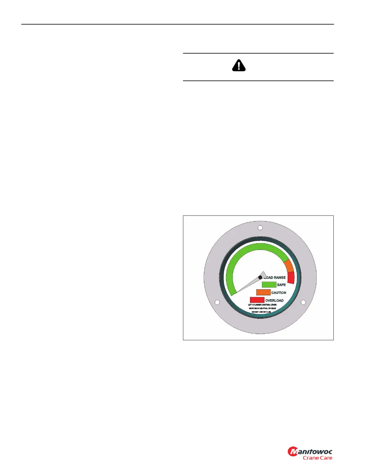
6. Monitor the load range gage located in the console as
the boom is extending. The gage is plumbed directly into
the lift cylinder pilot line and the pressure reading should
increase to what is defined as capacity load pressure as
the selected intermediate boom length and radius is
reached.
7. The intermediate boom length is determined by a line
and corresponding dimension decal on the side of the
second section boom. The chosen radius is measured
from the centerline of rotation to the loadline.
8. If the gage reading does not increase while extending,
lower the load to the ground and check the system
plumbing according to the hydraulic schematic.
Re-plumb the system according to the schematic and
illustrated parts page or replace faulty pressure gage.
WARNING
Before loosening any fittings, support the boom.

 Loading...


