National Crane Published 08/16/19 Control # 112-05 6-11
500E2 SERVICE MANUAL SWING
BEARING REPLACEMENT
Removal
1. Fully extend and set the outriggers enough to take up
the slack in the pads.
NOTE: Do not raise the machine on the outriggers.
2. Rotate the boom to about 10° off the rear position so that
the boom is clear of the boom rest.
NOTE: The lift cylinder pins need to be accessible from the
truck deck.
3. Elevate the boom slightly and shut down the engine.
4. Tag and disconnect the battery cables.
5. Remove the boom and lift cylinder following the
procedures outlined in “Boom Removal” on page 4-3.
NOTE: If equipped with a swivel, tag and disconnect all
hydraulic lines from the swivel on the carrier side.
Cap or plug all lines and openings. The swivel is
removed with the turret.
6. Attach a suitable lifting device to the turret. Remove any
slack in the sling. Do not pull up on the turret.
7. Remove all bolts and washers from the outer race of the
swing bearing.
8. Carefully lift the turret with bearing off the truck and set it
on blocking that will not allow the turret to tilt or shift.
Leave the lifting device attached.
NOTE: If the current bearing is to be reinstalled, mark the
position of the bearing on the turret before removal.
9. Remove all bolts from the inner race of the swing
bearing.
10. Lift the turret off the swing bearing and set on blocking.
NOTE: The bearing weighs about 415 lb (188.2 kg).
Check the bearing teeth for chipping or cracking. If any
evidence of these is found, replace the bearing. Ensure the
bolt holes are free of dirt, oil, or foreign material.
Installation
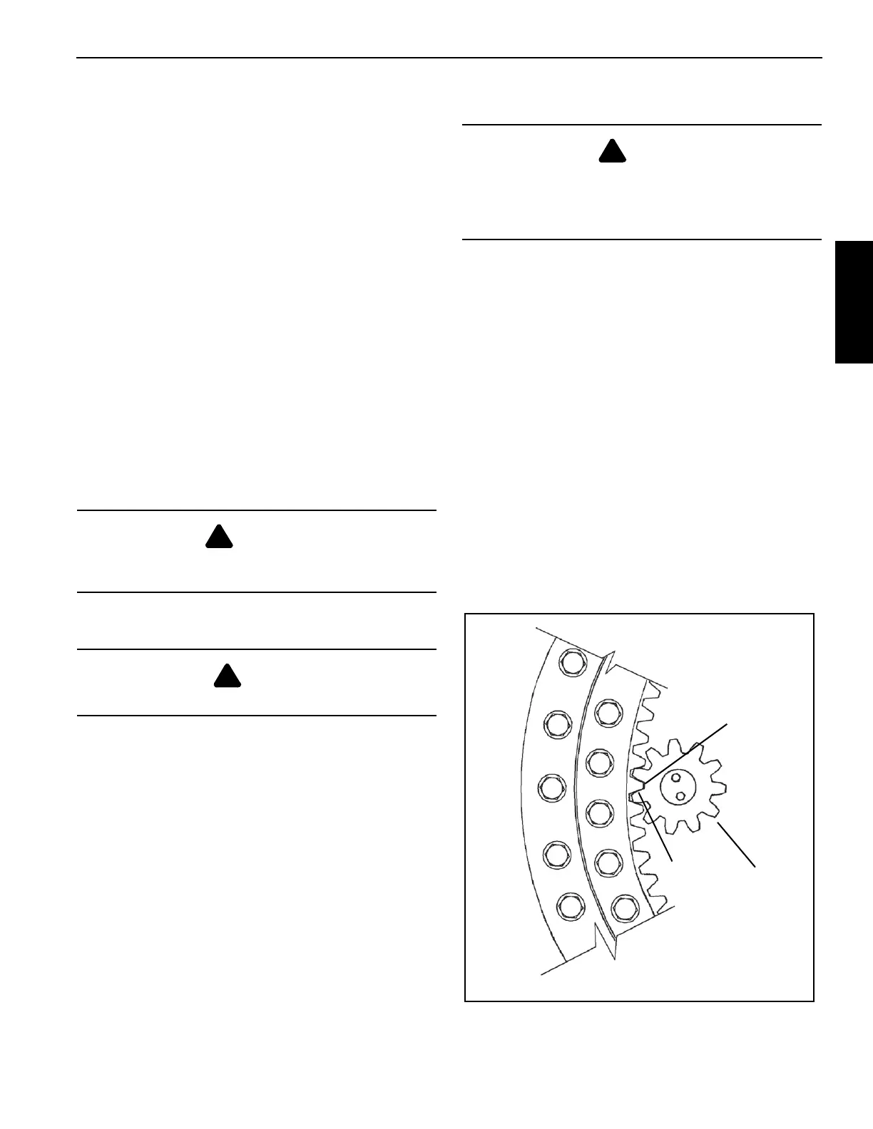
NOTE: If the current bearing is reinstalled, align the
marked teeth on the swing drive pinion shaft with
the marked teeth on the bearing.
1. Using an appropriate lifting device, set the turret on the
swing bearing. If the same bearing is being used,
position it as marked prior to removal.
2. Install new bolts and washers securing the bearing to the
turret. Refer to “Inner Race Torquing” on page 6-9.
3. Using an appropriate lifting device, align the turret over
the frame at the same position that it was before
removal.
4. Carefully lower the turret into position on the bearing
plate.
NOTE: If equipped, be careful not to damage the swivel
assembly.
5. Install all bolts and washers to secure the outer race of
the swing bearing to the T-box frame. Refer to “Outer
Race Torquing” on page 6-9.
DANGER
Ensure the lifting device is capable of supporting the
boom assembly.
DANGER
Ensure blocking material can support the turret.
DANGER
Do not reuse the swing bearing bolts. The swing bearing
is torqued to the applied torque of the grade 8 bolts. New
bolts ensure proper torque and bolt strength for securing
the swing bearing and turret to the frame.
0.008 Shim
Maximum
Eccentricity
Tooth
Pinion
FIGURE 6-5

 Loading...


