4-8 Published 08/16/19 Control # 112-05
BOOM 500E2 SERVICE MANUAL
Make certain anti-two-block cable is correctly on
sheave. Inspect from sheave case end.
36. Adjust slack out of extend and retract cables at hex nut
adjustment points. Slowly cycle boom in and out several
times. Torque cables per procedure located elsewhere
in this book.
Three Section Top/Bottom Pad Replacement
(Assembled Boom)
NOTE: Refer to Inner Wear Pad Calibration on page 4-8 of
this section to determine Wear Pad shim thickness.
Inspect top and bottom wear pads periodically for signs of
abrasion or excessive wear. Excessive is defined as:
• 3/16 of an inch (4.76 mm) from the original pad
thickness.
• Top rear pad thickness 0.75 inch (19.05 mm).
• Bottom front 1
st
section 1 inch (25.4 mm).
• Bottom front 2
nd
section 0.50 inch (12.7 mm).
• Uneven pad wear of 3/32 inch (2.38 mm) from side to
side on the wear pad.
If any of these conditions exist, the top and bottom pads can
be replaced without complete disassembly of the boom.
Top Rear Pad Replacement
NOTE: Refer to Inner Wear Pad Calibration on page 4-8 of
this section to determine Wear Pad shim thickness.
1. Retract boom completely.
2. Remove capscrews through access holes on top rear of
sections.
3. Remove wear pads and cam plates from the rear of the
boom through open winch mount end.
4. Note all pad locations and tag accordingly.
5. Inspect pads for wear using previously mentioned
inspection criteria.
6. Assemble top/rear wear pads to the top of the 2
nd
and
3
rd
boom sections with the cam plates.. Wear pads can
be inserted from the winch mount end of the boom.
Install capscrews through holes in outer boom sections.
7. The wear pad on each side at the top/rear of the boom
can be adjusted over a range of 3/16” (4.8 mm) by
rotating, end for end, the wear pad and plate or the wear
pads and plate independently. This is possible because
the holes in these parts are offset from the center. The
holes are 0.06" (1.5 mm) off center in the plate and 0.03"
(0.8 mm) off center in the wear pad. Various
combinations of rotation of these parts allow the
adjustment.
a. Adjust pads until they are within 0.03” (.8mm) off
center in the were pad. Various combinations of
rotation of these parts allows the adjustment.
b. Torque retainer capscrews to 110 ft-lb (149 N-m).
Failure to properly torque capscrews will cause loss
of preload and cause excessive side clearance
between sections.
Front Bottom Pad Replacement
NOTE: Refer to Inner Wear Pad Calibration on page 4-8 of
this section to determine Wear Pad shim thickness.
1. Extend boom approximately 4 feet (120 cm) out.
2. Using an appropriate lifting device, sling around the 3
rd
section boom and lift it up until weight is removed from
the bottom pads in the front of the 2
nd
and 1
st
boom
sections.
3. Loosen and remove the four capscrews holding the pad
doubler plate in between the 3
rd
and 2
nd
sections,
remove plate, remove pads from this plate. Note all pad
locations and tag accordingly.
4. Loosen and remove the four capscrews holding the
bottom front wear pads to the 1
st
section, remove pads.
Retract cable adjustment ends may have to be loosened
during this step. Note all pad locations and tag
accordingly.
5. If disassembly of cables was required:
- Replace all wear pads.
- Wear pad plate.
- Re-torque retract cables.
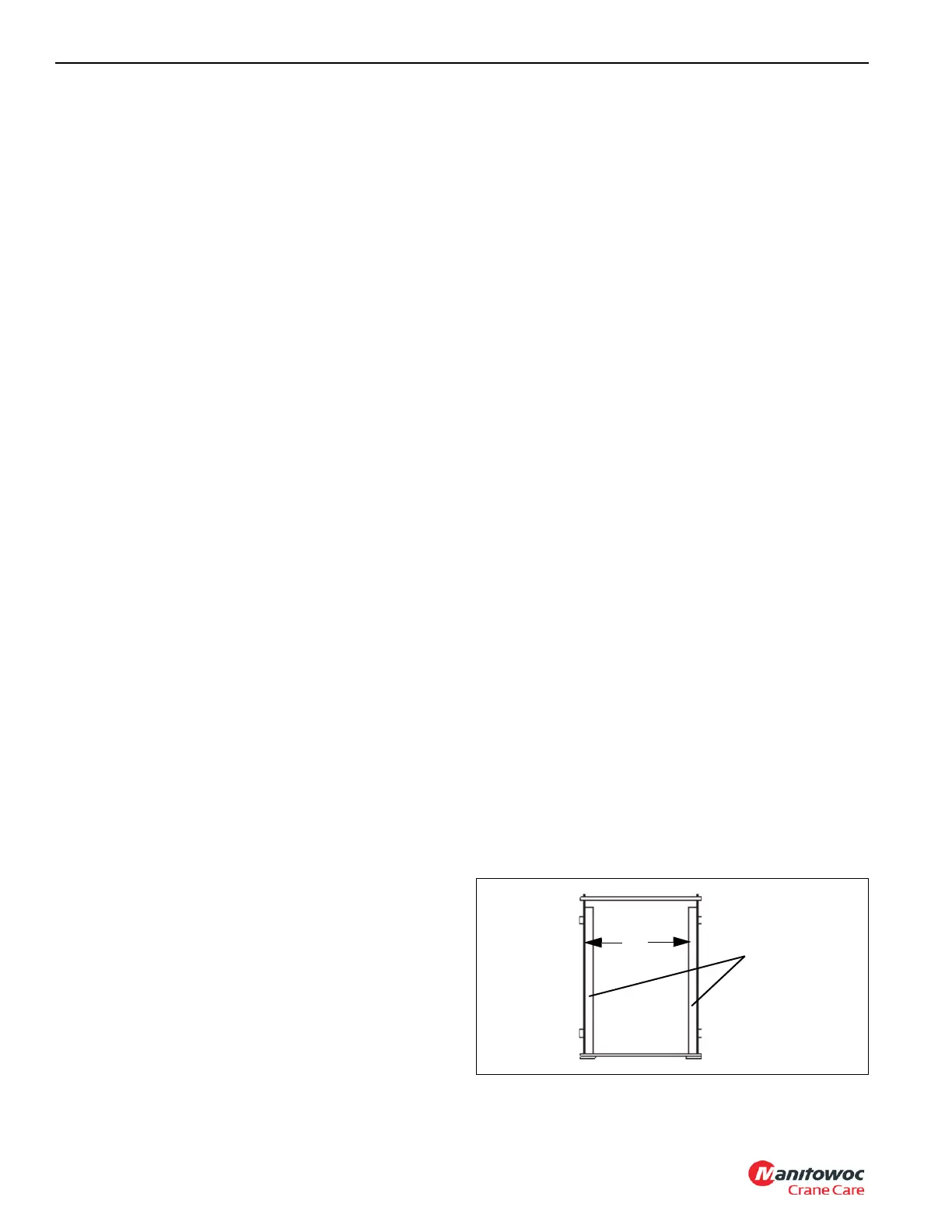
INNER WEAR PAD CALIBRATION
1. With a pair of inside/outside calipers, measure the inside
width of the outer section (Wi) at the front and back of
the boom and record the smallest measurement. If the
section has cylinder anchor bars, take a measurement
directly in front of these bars
W
i
CYLINDER
ANCHOR BARS
OUTER
SECTION

 Loading...


