National Crane Published 08/16/19 Control # 112-05 4-3
500E2 SERVICE MANUAL BOOM
1. Slightly tighten all cables. Then cycle the boom
approximately 4 feet (120 cm) out and in a few times to
equalize the extend and retract cable/ boom section
sequence positioning.
2. Fully retract boom. Do not induce and hold hydraulic
pressure. At full retraction, observing through the hoist
mount end of the boom, the second section should be
bottomed on the extend cylinder butt plate, and the third
section should be bottomed on the thick vertical side
plates welded to the inside of the second section.
NOTE: It is important to achieve these boom postitions
before torquing.
3. If the boom sections do not bottom out as specified
(boom is out of sequence), adjust cables to achieve
proper section positioning.
4. Torque retract cables to 6 ft-lb (8.13 Nm). Cable
adjustment point is located at the sheave case end of
the boom, on the bottom of the 1
st
section. Use the flats
at the front of the cable ends to keep the cables from
turning while torquing retainer nuts.
5. Torque extend cables to 20 ft-lb (27.11 Nm). Cable
adjustment point is located at the rear of the boom on
the cable anchor bar going through the hoist mount.
6. Repeat Steps 4 and 5.
7. Torque the retract cables to 12 ft-lb (16.26 Nm).
8. Torque the extend cables to 30 ft-lb (40.67 Nm).
9. Cycle the boom fully, check that all cables are torqued
properly and that all sections are retracted completely,
then add jam nuts to all cables. All threaded cable ends
must be equipped with retainer nuts and jam nuts.
HOIST REMOVAL
1. Extend and set the outriggers.
2. Fully retract the boom and place in a horizontal position.
3. Remove hook block or downhaul weight. Wind up rope
on hoist drum and stow wedge socket on pegs provided
on 1
st
section. Shut down truck engine.
4. Tag and remove the hydraulic hoses (the inside hose
“up” and the outside “down”). Cap all hoses.
5. Pull hydraulic hoses through the access hole towards
turret.
6. Remove Rope Guard mesh and attach suitable lifting
device to hoist and take up the slack.
7. Remove 6 mounting capscrews and washers (3 on each
side).
8. Lift hoist clear of boom and secure to a suitable holder.
DANGER
Do not, under any circumstances, work at an elevated
height without using proper fall protection as required by
local, state or federal regulations.
CAUTION
The combined weight of the hoist and 325 ft. of wire rope
is 660 lbs (300 kg).
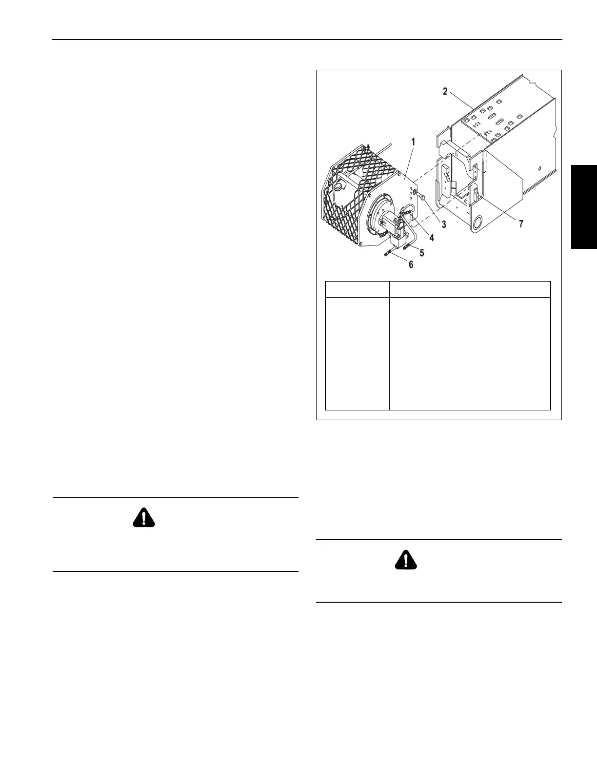
Item Component
1Winch
2 Boom
3 Capscrew (6 plcs)
4 Hyd Hose 1
5 Winch Down Hose 2
6 Winch Up Hose 3
7 Winch Alignment Ears

 Loading...


