National Crane Published 08/16/19 Control # 112-05 4-15
500E2 SERVICE MANUAL BOOM
break packing gland loose. Remove holding valve and
extend and retract plugs from butt plate and pull packing
gland out by hand.
7. As soon as the packing gland is sufficiently loosened,
properly support the rod assembly and carefully remove
it by hand. Place rod assembly on supports. Exercise
caution in the support and removal of the rod assembly
as damage to the chrome surface requires rod assembly
replacement.
8. Disassemble the piston set by removing nut, replace
worn or damaged parts.
NOTE: Note: Loctite 680 is used during original assembly
to secure nut to shaft.
9. If necessary, heat nut to 400-500° F (204-260°C) to
facilitate removal. If heat is necessary for removal,
discard nut and replace with new equivalent nut as well
as worn or damaged parts.
10. Wipe and inspect all cylinder internal and external
surfaces for damage.
11. Remove seals and bearings from packing gland and
piston. Replace all seals and bearings.
12. Inspect wear pad on barrel assembly and replace as
required.
Extend Cylinder Assembly
1. Reassemble shaft and piston set assembly in the proper
order with internal round section ring, assembled
packing gland, stop tube, piston to shaft o-rings,
assembled piston, and locknut. Loctite locknut onto
shaft using type 680 according to Loctite
recommendations. Torque locknut to 300 ft-lbs (407Nm).
2. De-burr ring groove edge in barrel assembly and inspect
all internal and external surfaces for damage.. Failure to
do so will damage packing gland and or barrel assembly
when packing gland is installed.
3. Grease piston assembly and install the shaft assembly
with piston, o-ring, stop tube, packing gland, internal
round ring into barrel assembly.
4. Using special drive tool, drive the packing gland into the
barrel assembly.
5. Insert one end of round ring into groove in barrel
assembly and spiral the ring into groove with straight
blade screw driver.
6. Cycle test cylinder to ensure no leaks exist. Support end
of cylinder as it extends and retracts.
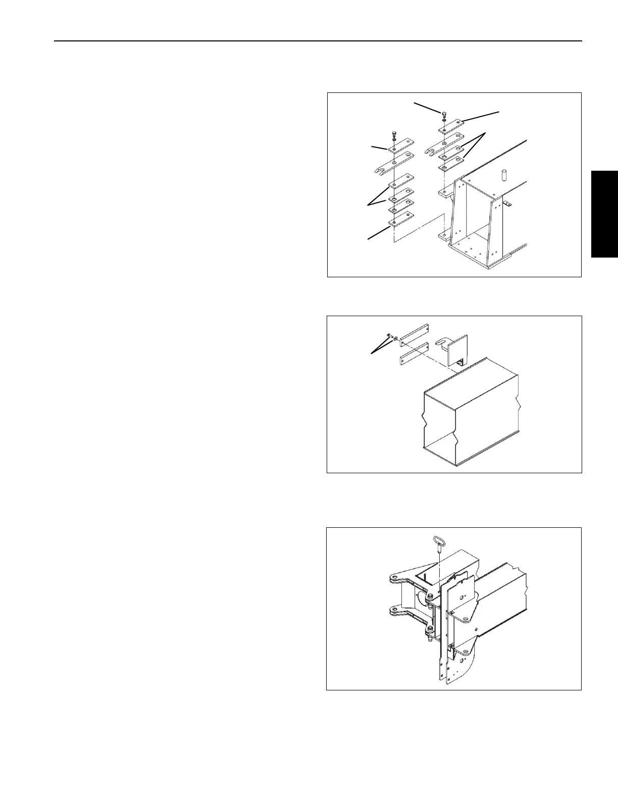
JIB INSTALLATION AND ADJUSTMENT
1. Loosely bolt the two ear assemblies with shims and bars
as shown to the side of the first boom section.
NOTE: Note: All measurements are in inches (mm).
2. Loosely bolt the hook assembly to the side of the first
boom section.
3. Extend the boom approximately one foot (300 mm).
4. Using an overhead hoist, lift the jib assembly and align
and pin the jib to the boom sheave head.
5. With jib pinned to the sheave head, swing the jib parallel
to the boom and install the pin which keeps the jib from
3/4” Grade 5
(Typ 4 Plcs)
0.38 (10) Bar
0.38 (10)
Bar
0.06 (1.6)
Shims
0.38 (10)
Bar
0.06 (1.6)
Shims

 Loading...


