6-4 Published 08/16/19 Control # 112-05
SWING 500E2 SERVICE MANUAL
14. Remove the retaining ring (43) from the input carrier
(44), remove the output sun gear (45), and inspect for
wear and replace as necessary.
15. Remove retaining rings (48), press out the planet pin
(53), remove the planet gear (51), and needle bearings
(52), inspect for unusual wear. Replace as required.
16. Remove the pinion locking bolt (46) from the out put
planet carrier (47). Loosen the pinion bolt (49).
17. Remove the retaining rings (48). Lift output planet set
out of the housing (1). Press out the planet pin (57);
remove the planet gear (55) and needle bearings (54).
Inspect for unusual wear. Replace as required.
18. Remove the inboard bearing (11) and inspect for wear.
19. Remove the pinion shaft (6) from the housing (1) and
inspect the pinion shaft, seal, and bearing for wear.
20. Remove outboard bearing (7) and seal (10). Inspect for
wear and replace if necessary.
Tulsa Swing Drive Assembly Procedure
1. Press the inboard and outboard bearing cup (12) into the
gear housing (1) if replaced.
2. Grease pack the bearing cones items (7) with EP 2
before installation.
3. Install the outboard cone (7) into the outboard cup (12).
Press the seal (10) into the gear housing (1) from the
outboard side.
4. Slide the output pinion (6) into the housing (1) from the
outside.
5. Install the inboard bearing cone (11).
6. Separate the gear set (4) into sections.
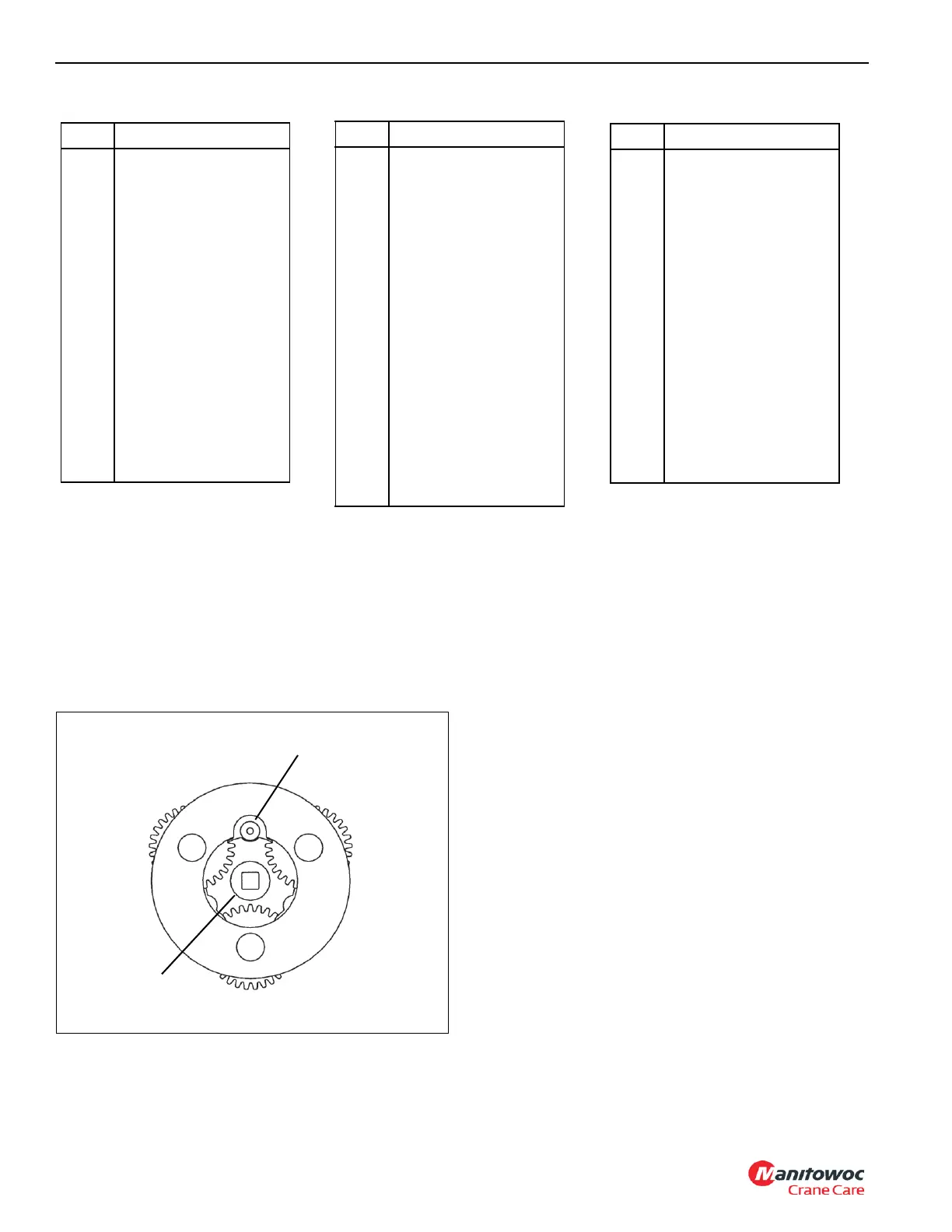
7. Apply Loctite to the threads of the pinion bolt (49). Install
the output carrier (47) into the gear housing (1).
a. Tighten the pinion bolt halfway, check the alignment
of the output carrier (47) with the spline on the
pinion shaft (6), and then tighten the pinion bolt the
rest of the way.
b. Torque the pinion bolt to 50 ft-lb (68 Nm), loosen
and re-torque until the pinion locking bolt aligns with
Item Component
1 Gear Housing
2 Brake Housing
3 Motor Adapter
4 Gear Set
5 Brake Piston
6 Pinion Shaft
7 Outboard Bearing
8 Brake Driver
9 Thrust Plate
10 Seal
11 Inboard Bearing
12 Bearing Cup
15 Spring
16 Stator Plates
17 Friction Plates
19 Back-up Ring
20 O-ring
21 O-ring
22 Back-up Ring
23 O-ring
24 Fill Plug
26 Drain Plug
27 Socket Head Capscrew
28 Socket Head Capscrew
32 Breather
34 Thrust Washer
35 Grease Fitting
Item Component
36 Snap Ring
37 Retaining Ring
41 Sun Gear
43 Retaining Ring
44 Input Carrier
45 Sun Gear
46 Locking Bolt
47 Output Planet Carrier
48 Retaining Rings
49 Pinion Bolt
51 Planet Gear
52 Needle Bearings
53 Planet Pin
Item Component
Pinion Locking Bolt
Pinion Bolt

 Loading...


