9-36 Published 08/16/19 Control # 112-05
CRANE INSTALLATION 500E2 SERVICE MANUAL
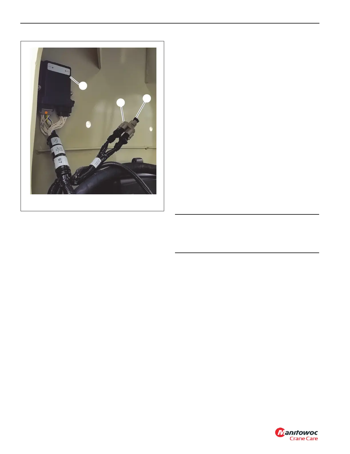
2. Remove the terminating resistor from the Deutsch
splitter (Figure 9-4).
3. Install the terminating resistor in to the diagnostics
cable.
4. Connect the diagnostic cable to the splitter.
5. Connect the serial port to the CAN to USB adapter
cable.
6. Connect the USB adapter cable to the laptop.
7. Engage the PTO.
8. Turn the crane ignition switch to the RUN position. Do
not start the engine.
Setting Up the CAN Bus System
1. Start the laptop and launch the CAN bus system
software.
2. Use the HED software to set EEPROMs for engine type,
throttle calibration, and OMS setup.
3. Use the software debug feature to verify that the setup is
complete.
4. Disconnect and close the CAN bus system software
application.
5. Disconnect the diagnostic cable from the laptop and
crane. Install the terminating resistor in the splitter.
6. Disengage the PTO.
CAN Bus System using Programming
Button
The programming button is located on the driver’s side
console behind the sliding door above the override key
switch.
Refer to the A-Frame Crane Software Specification and
Configuration specification for detailed instructions about
using the push button method of initializing the CAN bus
system.
CAUTION
Only trained personnel should use the programming
button to initialize the CAN bus system. Incorrect setup of
the CAN bus system can cause the throttle pedals to be
inoperable.

 Loading...


