National Crane Published 08/16/19 Control # 112-05 3-5
500E2 SERVICE MANUAL ELECTRIC SYSTEM
.
9. When the pressure reaches capacity load pressure, the
overload system should activate and boom extension
will stop. This is defined as trip pressure. This point
should be at or very close to the red/yellow color change
on the load range gage.
10. Trip pressure should be reached as the boom extension
reaches the chosen radius. If the overload system trips
before the chosen radius is reached or allows extension
beyond the chosen radius, adjustment is required. If the
system is activated before trip pressure is reached,
lower the load and turn the knurled collar on the HCA
pressure switch clockwise to increase trip pressure.
11. When the gage reaches trip pressure, turn the setscrew
counterclockwise until the system solenoid is
deactivated and tighten the locking nut.
12. Retract the boom until the pilot pressure is reduced
enough to reactivate the system solenoid. The hydraulic
capacity alert indicator light will go out when the solenoid
is reactivated.
13. Check the trip pressure setting by extending the load
until the chosen radius is reached. As the chosen radius
is reached, the system solenoid should be deactivated
and the indicator light should come on. Readjust switch
head if trip pressure is not correct.
14. Once proper adjustment is verified, return the boom to a
firmly supported position, stop the truck engine and
replace covers.
JIB LOAD LIMITING DEVICE
The jib load limiting device is an electromechanical
maximum capacity sensing system that stops normal crane
functions which cause an overload condition when the
maximum capacity of the jib is exceeded. In the event that an
over capacity condition occurs, the jib load limiting device is
actuated by a load cell which causes the boom down, extend
out, and hoist up functions to become inoperative. On jibs
with a manually extendable section, a configuration switch
operated by the extension retaining pin distinguishes
between an extended jib and a retracted jib. This system
allows for continued operation of the hoist down, boom up,
and boom retract. This allows the operator to bring the load
to a shorter operating radius or set the load down in order to
eliminate an overload condition. Once the overload has been
reduced, normal operation can be resumed. This system
uses the work port unloader solenoid in the anti-two-block
system as the hydraulic system dump circuit.
When trip force is reached, the jib load limiting device breaks
electrical continuity to the work port unloader solenoid in the
main control valve. When power is removed from this
solenoid, the unloader valves allow the oil flowing to hoist up,
telescope out and boom down to flow to tank. This path to
tank will prevent further operation of these functions. When
the overload condition is corrected by hoisting down,
retracting the boom, or raising the boom, the jib load limiting
device allows the work port unloader solenoid to be powered
thereby allowing the crane to function normally.
During operation at near capacity loads, care must be taken
to operate the controls smoothly or the system may be
shocked into the dump mode prematurely.
Single Character Display
The electronics box of the jib load limiting devices equipped
with a single character display that provides the following
information:
• startup codes
• table number selected
• current load reading
• current limit value
• error codes
• current angle reading.
On power-up, the unit first displays the startup codes. The
startup codes can be a sequence of up to four single digits,
but is usually be only one digit which is a "2". Each number is
displayed for 1/2 second. The codes are:
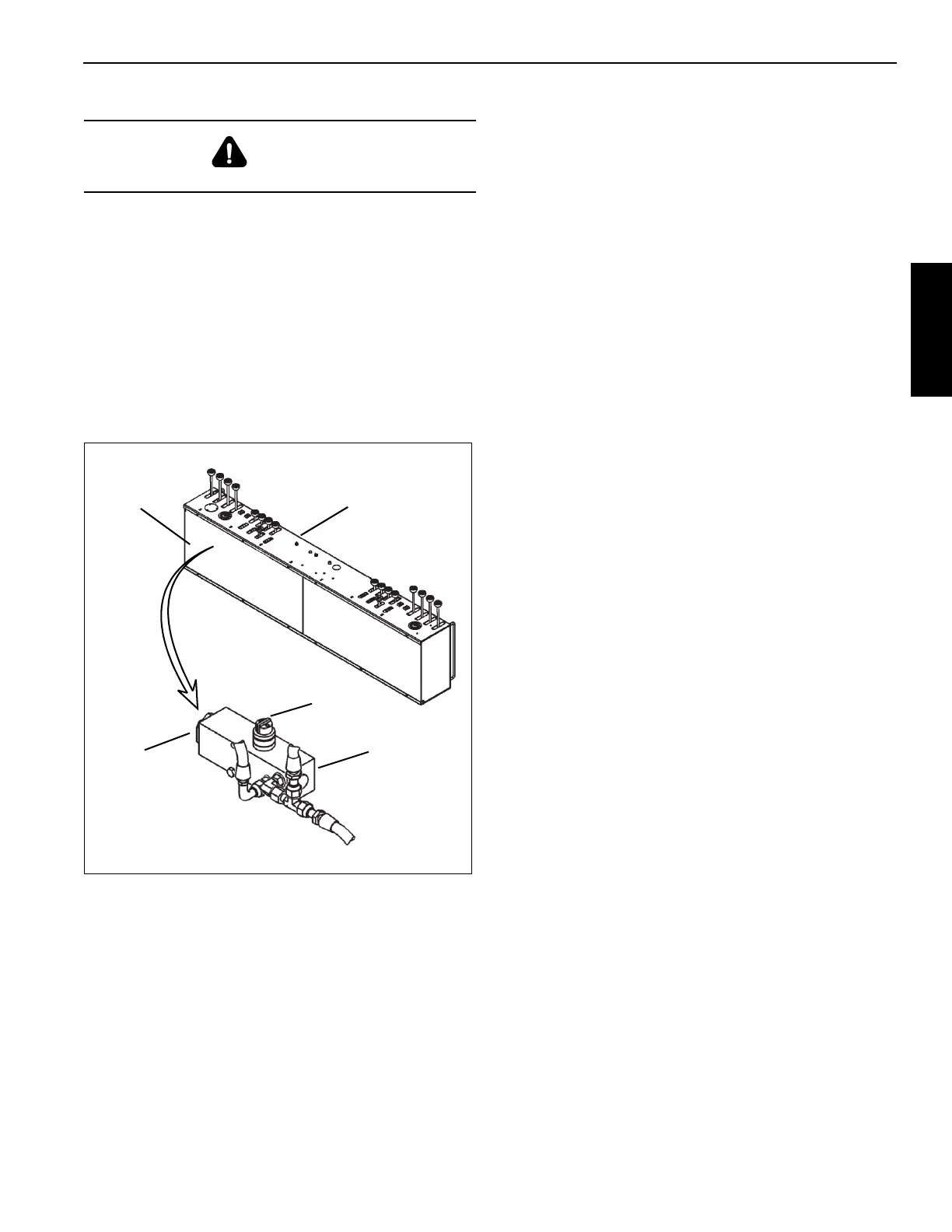
WARNING
Before loosening any fittings, support the boom.
Cover
HCA pressure
switch
Relief
Operators
Console
Adjustment
Knob

 Loading...


