3-6 Published 08/16/19 Control # 112-05
ELECTRIC SYSTEM 500E2 SERVICE MANUAL
• (1) Indicates the unit is being initialized. This only
happens the first time the unit is powered up after it is
programmed.
• (2) Indicates that the previously stored table is being
erased. This is displayed when the unit is powered on
and the switches are not set for the new table numbers.
• (3) This is displayed only before a new table number is
stored. The “2” is displayed first.
• (8) The switches are set up with the new table number
and the old number is erased. On the next power on, the
new table number is read in and stored.
After the startup codes, the table number is displayed in the
form of three sequential single digits. The first digit is always
zero. The digits are be displayed for about 1 second each.
After the table number is displayed, the display starts to
sequence through the following information. After reaching
the end of the sequence, the display starts again at the
current load reading.
• Current load reading (lbs.):
- 4 digits, decimal point on
• Current limit value (lbs.):
- 4 digits, decimal point flashing
• Error codes (only if an error exists):
- 4 digits, first and last digits are blanks.
- 0-invalid table number,
- 1-load readings higher than the limit.
• Current angle reading:
- 4 digits, decimal point off, displays in tenths of
degrees.
Jib Load Limiting Device Troubleshooting
See chart in Section 8 of this manual.
OUTRIGGER MONITORING SYSTEM (OMS)
(OPTIONAL—STANDARD IN NORTH
AMERICA)
Operation
The Outrigger Monitoring System (OMS) aids the operator in
ensuring that the crane is properly setup on outriggers and
stabilizers. The OMS utilizes one sensor in each outrigger
and one proximity switch in each horizontally extending
stabilizer to identify when the outriggers and stabilizer beams
are extended to a point in which they provide maximum
stability.
Maintenance
Outrigger Cylinder Length Sensor
(Version 1)
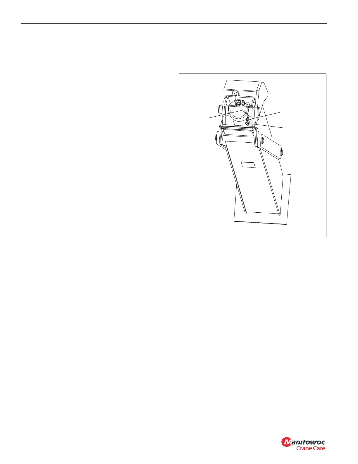
Remove
1. Fully retract outriggers.
2. Disconnect electrical connector (1, Figure 3-1) at
sensor.
3. Remove setscrews (2, Figure 3-1) securing sensor
holding plate.
4. Slide sensor (3, Figure 3-1) out of sensor holding
bracket.
Install
1. Fully retract outriggers.
2. Slide sensor (3, Figure 3-1) into holding bracket.
3. Using the two setscrews (2, Figure 3-1) and sensor
holding bracket, secure sensor to the hydraulic cylinder.
4. Connect electrical connector (1, Figure 3-1) to sensor.
5. Calibrate sensor; refer to Calibrate, page 3-6.
Calibrate
Calibrating the cylinder length sensor requires a laptop
equipped with the HED Conductor software and a USB cable
connector (p/n 80009992). Contact your National Crane
distributor for further assistance.

 Loading...


