National Crane Published 08/16/19 Control # 112-05 3-7
500E2 SERVICE MANUAL ELECTRIC SYSTEM
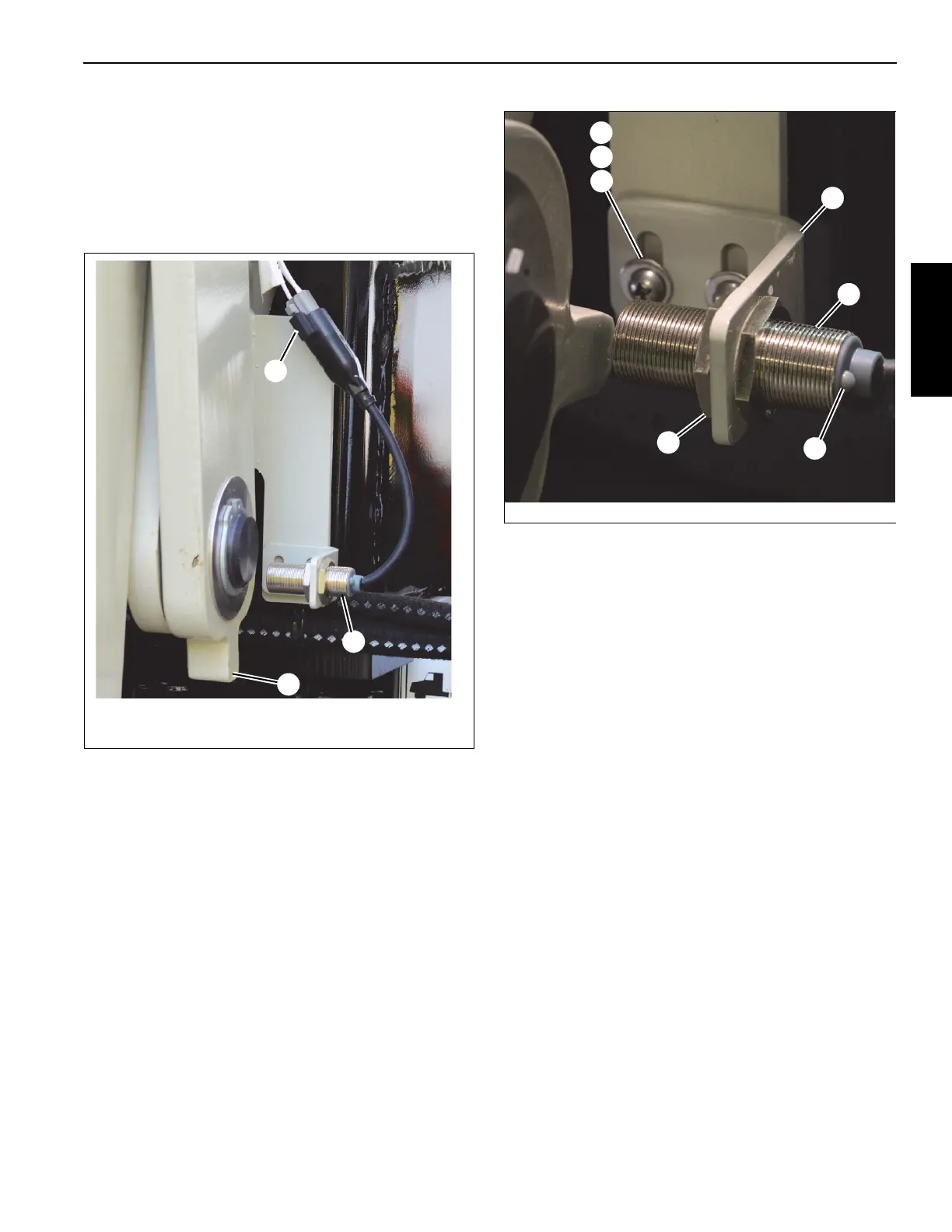
Outrigger Proximity Switch (Version 2)
On newer versions of the crane, the OMS and RCL use
proximity switches to determine if the outriggers are fully
extended. The switches are located between the operator’s
cab and A-frame outriggers. The proximity switch (1,
Figure 3-2) uses a tab (2) on the outrigger arm to determine
when the outrigger is fully extended.
Remove
1. Fully retract the outriggers.
2. Disconnect the proximity switch (1, Figure 3-2) and
sensor plug (3).
3. Remove capscrews (1, Figure 3-3), lockwashers (2),
and nuts (3) to remove plate (4) and proximity switch (5)
from chassis.
4. Loosen jam nuts (6) and remove proximity switch (5)
from plate (4).
Install
1. Fully retract the outriggers.
2. Install proximity switch (5) on plate (4) using two jam
nuts (6).
3. Install switch (5) and plate (4) on chassis using
capscrews (1), lockwashers (2), and nuts (3).
4. Connect proximity switch (Figure 3-2) to sensor plug.
NOTE: The proximity switch should be a maximum of 6.4
mm (0.25 in.) from the outrigger tab.
5. With power on, fully extend the outriggers. When active,
the LED light (7) on the proximity switch illuminates
constant yellow. Depending on how the vehicle is
equipped, verify that the proximity switch output is
working as follows:
- If equipped with Outrigger Monitoring (OMS) and
HCA systems, make sure the outrigger status
indicator on the operator’s console turns from
FIGURE 3-2
2
3
1
9365
For illustration purposes only.
Your crane may differ.

 Loading...


