National Crane Published 08/16/19 Control # 112-05 9-19
500E2 SERVICE MANUAL CRANE INSTALLATION
6. For a wet mount, a gasket is required for the mounting
flange to PTO gearbox interface. Dry mount does not
require a gasket.
7. Torque the mounting flange nuts to 50 ft. lbs (222 Nm).
NOTE: Some of the pipe fittings used are sealed by means
of two threaded tapered sections, one male and
one female. When these two tapers meet, you will
note a sudden increase in the force required to
screw the fittings together. This is true of all tapered
pipe threads. Further tightening will not only fail to
increase the pressure tightness of the joint, but
may ruin the connections and make correct
assembly impossible.
Other fittings are of the o-ring boss type. These are
installed by first screwing the lock nut flush to the
upper thread land and installing fitting into port until
the nut contacts the surface of the port. Adjust
fitting to desired direction. Tighten locknut.
Most pressure fittings are the O-ring face seal
types. A small O-ring is compressed between the
male and the female fittings of the joint. Be sure the
O-ring is present on the fitting and seated properly
in its groove before the fittings are tightened.
8. Remove the dust covers from the pump inlet and outlet
and make sure that the suction and pressure sides of the
pump are correct.
NOTE: An arrow is cast into the rear of the pump housing
to identify rotation. Make sure the rotation is
correct.
Rotate the pump in the direction as the PTO. Rotate the
pump in the mounting bracket so suction side is toward
the reservoir suction port.
REINFORCING/AFTER FRAME EXTENSION
1. Refer to “Truck Frame Strength” and “Section Modulus”
tables. Determine section modulus by actual
measurement of the truck frame. If reinforcing is
required, always use at least 100,000 psi (758 MPa)
steel to minimize the amount of reinforcing required. Use
Grade 90 weld material for any welding to be done.
2. Strip the frame of obstructions in the area to be
reinforced or extended, one side at a time. If the truck
frame cross members are bolted in, remove the bolts.
Do not attempt to remove any rivets.
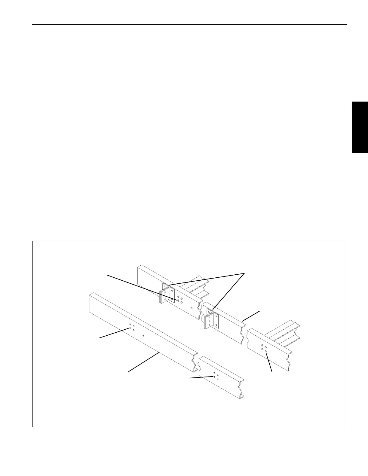
3. Place the reinforcing on the truck frame and clamp in
place. Mark the location of any rivets by striking the
outside of the reinforcing over the rivet area so that the
rivets make an impression on the inside of the
reinforcing. Mark the approximate location of the crane
mounting anchors so that no obstructions exist. Remove
the reinforcing and drill or torch cut clearance holes for
bolts or rivets. See Figure A.
The bolt hole clearance is
1/16 (1.52) to 1/8 (3.17) in
diameter larger than the
bolt shank
(Ref) Reinforcing
The rivet hole clearance
is 1/2 (12.7) in diameter
larger than the rivet head
Do not remove the rivets.
Clamp on reinforcing and strike
the reinforcing in this area to
mark the location of rivets
Remove bolts, clamp on
reinforcing, and mark the
bolt hole location from
the inside of the frame
Plan the location of the crane
mounting anchors so they don’t
interfere with the bolts, etc.
(Ref) Truck frame
NOTE: All dimensions
are inches (millimeters)
Figure A

 Loading...


