Grnd
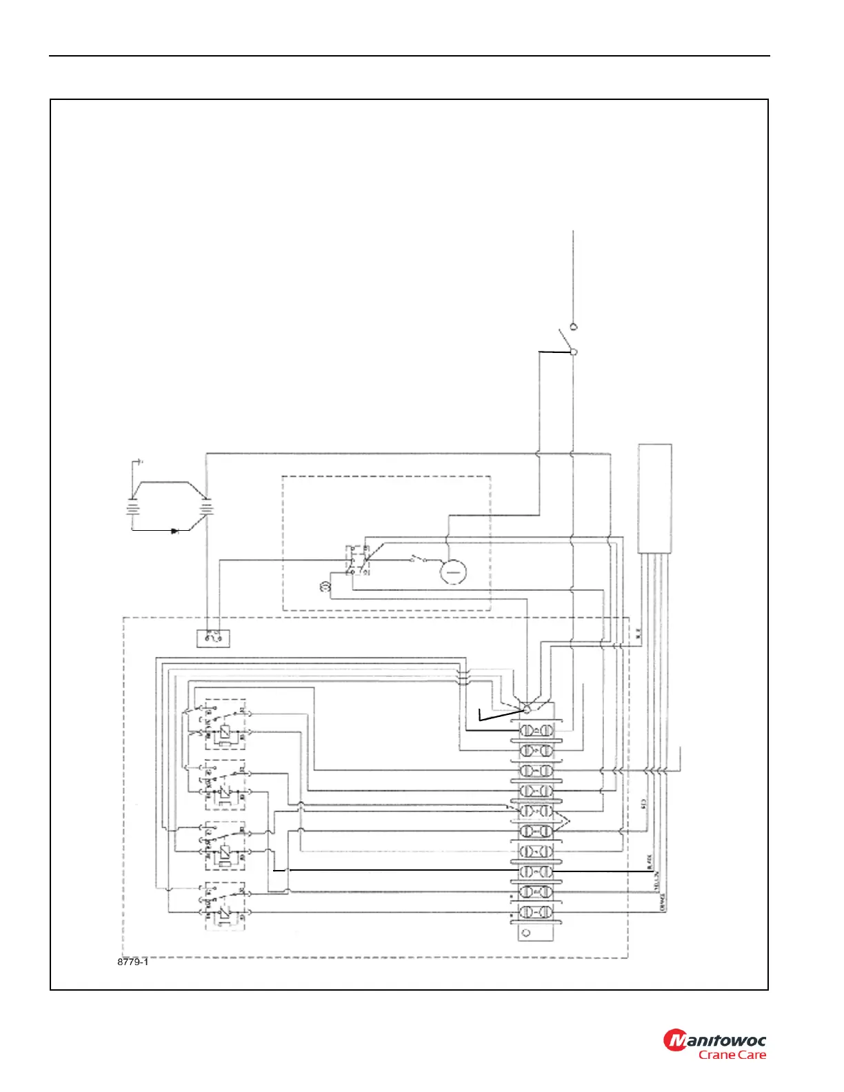
FIGURE 3-9 continued
(See Note 2)
Remote
Indicator
Light
Neutral Safety Switch
Truck Cab
(After Remote
Installation)
On
Remote
Power
Switch
Existing*
Ignition
Switch
Wire
(Switch
Side)
Existing Start
Wire from
Ignition Switch
OPTION GROUP
(Remote Control Engine
Compartment wiring Diagram)
sheet 2
Aux Battery
(Not required on
all units)
Grnd
12VDC
12VDC
Off
Clutch
Switch
Truck
Ignition
Switch
To Tr u c k
Solenoid
(Start)
5 Conductor Cord
from Remotes (Radio
Receiver or Relay
Chassis)
* Connect to Existing Ignition
Switch Wire in Cab (Solenoid Side)
NOTE: 1. All grounds must be referenced to the negative side of the battery.
2. Start circuit wire from terminal 10 to neutral safety switch is only to be
installed if start relay is installed on chassis.
3. Items denoted with (*) is the existing ignition wire cut for remote
installation.
To
Throttle
Switch +12VDC
Bat Grnd
Light Grnd
Grnd
Terminal
# 87 Start
# 87 Throttle
# 86 Ignition & Remote Ignition
# 86 Throttle
# 86 Start
# 87 Ignition & Remote Ignition
# 30 Ignition
# 30 Remote Ignition
# 30 Throttle
# 30 Start
# 85 Ignition
# 85 Throttle
# 85 Remote Ignition
# 85 Start
Start
Throttle
Remote
Ignition
Ignition
C. Breaker
Remote Relay Mounting Board in Engine Compartment

 Loading...


