Manitowoc Published 04-06-18, Control # 231-14 4-125
MLC650 VPC-MAX™ OPERATOR MANUAL SET-UP AND INSTALLATION
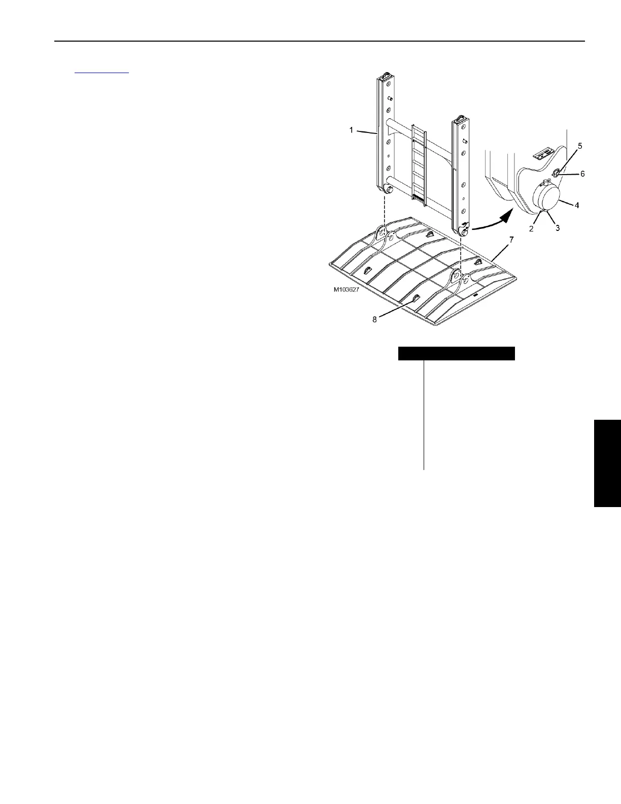
See Figure 4-105 for the following procedure.
7. Set the auxiliary frame assembly on the foundation while
holding the auxiliary frame (1) upright with the assist
crane.
8. Remove the cotter pins (2) from each of the retaining
pins (3).
9. Remove the retaining pins from the clevis pins (4).
10. Remove the clevis pins.
11. Remove the lynch pins (5) from each of the secondary
pins (6).
12. Remove the secondary pins.
13. Hoist with the assist crane to remove the auxiliary frame
from the pad (7).
14. Reinstall the clevis pins, retaining pins, cotter pins,
secondary pins, and lynch pins to the auxiliary frame.
15. Prepare the auxiliary frame for storage or shipping as
necessary.
16. Attach two more SL 4 slings to the assist crane.
17. Attach the four SL 4 slings to the pad at the lifting
lugs (8).
18. Prepare the pad for storage or shipping as necessary.
Item Description
1 Auxiliary Frame
2 Cotter Pin (qty 8)
3 Retaining Pin (qty 4)
4Clevis Pin (qty 2)
5 Lynch Pin (qty 4)
6 Secondary Pin (qty 2)
7Pad
8 Lifting Lug (qty 4)
FIGURE 4-105