Manitowoc Published 04-06-18, Control # 231-14 4-19
MLC650 VPC-MAX™ OPERATOR MANUAL SET-UP AND INSTALLATION
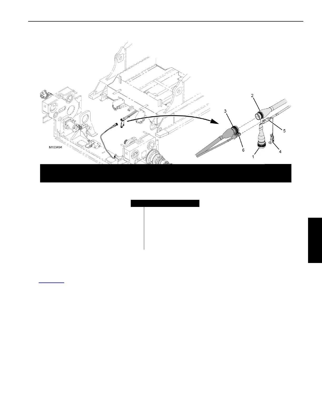
Connecting the Electrical Cables
See Figure 4-21 for the following procedure.
1. Remove the dust cap (1) from electrical plug WVB1 (2).
2. Connect electrical plug WVB1 to electrical plug
WVH1-P1 (3) on the actuator.
3. Remove the terminating resistor (4) from electrical plug
WVB2 (5) and mate the resistor to the provided dust
cap.
4. Connect electrical plug WVB2 to electrical plug
WVH1-P2 (6) on the actuator.
FIGURE 4-21
Item Description
1Dust Cap
2 Electrical Plug WVB1
3 Electrical Plug WVH1-P1
4 Terminating Resistor
5 Electrical Plug WVB2
6 Electrical Plug WVH1-P2