MAXDATA PLATINUM Server Board User’s Manual
8
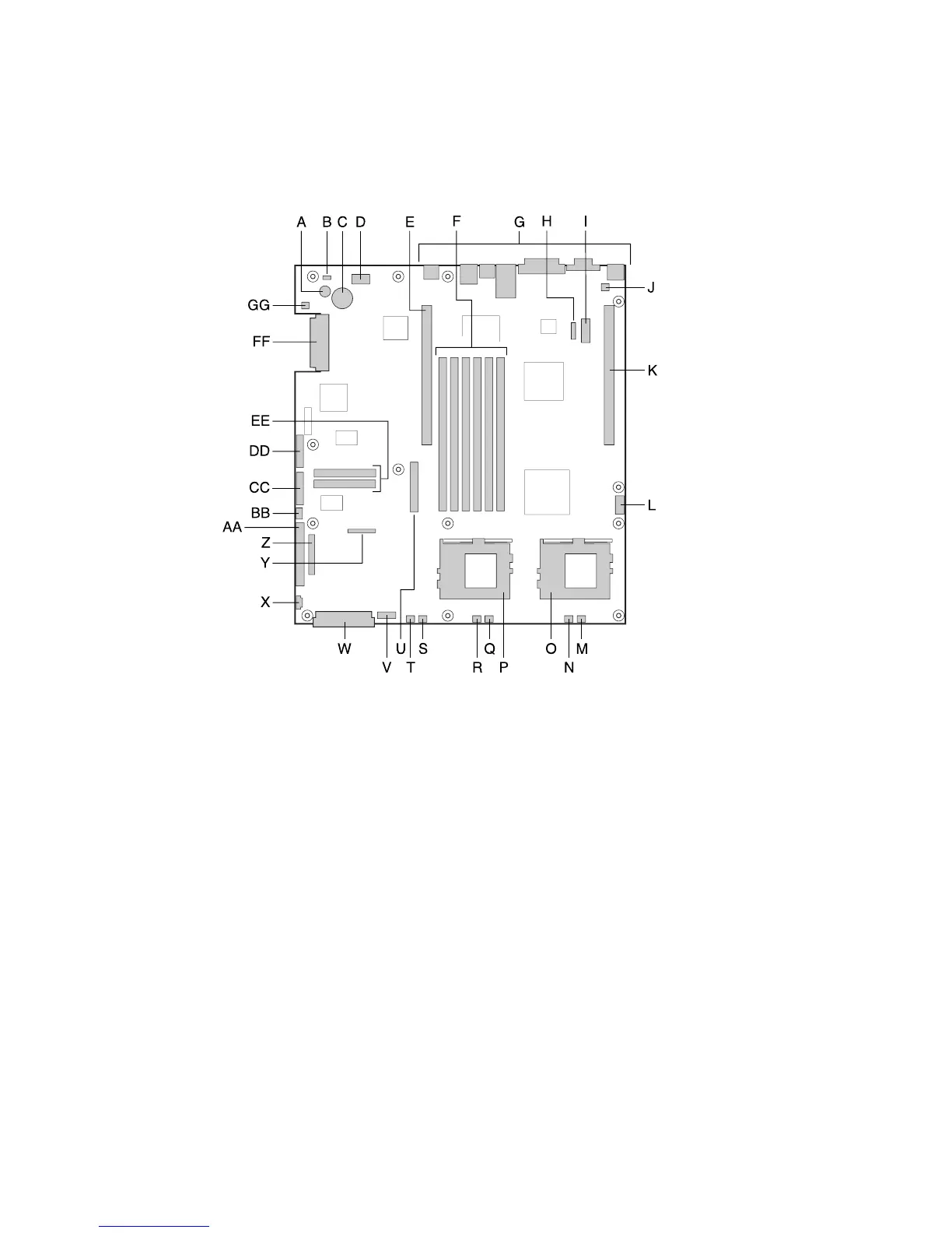
Server Board Connector and Component Locations
The SCB2 comes in both SCSI and ATA versions. Figure 1 is a composite view of both versions.
R. CPU 1 fan connector
S. Sys fan 1 connector
T. Aux fan connector
U. Floppy drive connector
V. Fan module connector
W. Main power connector
X. Auxiliary signal connector
Y. Floppy/FP/IDE connector
Z. Alternate front panel connector
AA. ATA/IDE connector
BB. IPMB connector
CC. SSI front panel connector
DD. Configuration jumper block
EE. ATA-100 connectors (ATA version only)
FF. SCSI connector (SCSI version only)
GG. Hard Disk Drive LED header
A. Speaker
B. ID LED
C. Battery
D. Diagnostic LEDs (POST code)
E. 66 MHz/64 Bit PCI riser slot (full height)
F. DIMM slots
G. I/O ports
H. ICMB connector
I. COM 1 serial header
J. Chassis intrusion connector
K. 66 MHz/64 Bit PCI riser slot (low profile)
L. USB 3 & 4 header
M. Sys fan 3 connector
N. CPU 2 fan connector
O. Secondary processor socket
P. Primary processor socket
Q. Sys fan 2 connector
Figure 1. Server Board Connector and Component Locations