CONTROLS, CONNECTORS, INDICATORS AND MENUS
AVTM246004 BITE 2/2P Rev 4 July 2011
15
Receiver Charger On/Off Indicator—LED illuminates when
the receiver is plugged into the receiver and the charger is
energized. It also indicates the state-of-charge of the receiver
battery. While the battery is charging, the LED remains
constant; when the battery is fully charged, the LED blinks.
Indicator Lamps:
CURRENT READY—Illuminates after the coupling
capacitors in the transmitter are charged to the bus
voltage. A delay timer allows current flow to the
battery under test.
POWER—Illuminates whenever the Power Switch is in
the | (ON) position and the unit is powered by 120 V
(230 V) ac line voltage
OVER VOLTAGE—Indicates that the voltage across the
current source leads is greater than 275 V dc. (The
READY light will go out and the current flow to the
battery will stop when an over-voltage condition
occurs.)
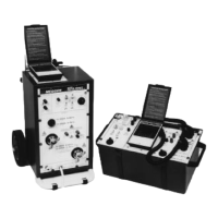
Transmitter
Connector Panel
Power module—The transmitter power module comprises
the following components:
J1 receptacle—The standard power cord supplied with
the instrument is inserted into this 120 V/60 Hz (230
V/50 Hz) receptacle for ac power.
F1 Fuse carrier/voltage selector—The fuse carrier is
removed as needed to replace fuses. The arrow located on
the connector panel directly to the left of the J1 receptacle
should point to the indicator on the fuse carrier that
corresponds to the proper voltage (120 V or 230 V). See
Figure 3-3.
J2 connector—The transmitter current source leads are
connected from this connector to the battery under test.
J3 connector—The receiver battery is charged from this
connector to J3 on the receiver to charge its battery.
www.GlobalTestSupply.com
Find Quality Products Online at: sales@GlobalTestSupply.com