EasyManuals Logo

Mercury 40 Service Manual

Mercury 40
599 pages
To Next Page IconTo Next Page
To Previous Page IconTo Previous Page
Page #239 background imageLoading...
Page #239 background image
CYLINDER HEAD
90-828631R3 MARCH 1999 Page 4A-43
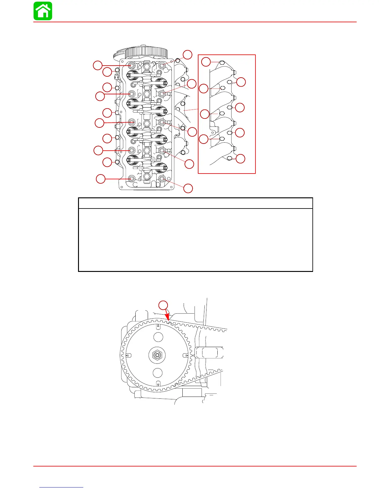
3. Torque center bolts in sequence and in two steps, than torque the Cylinder Head and
carburetor flange bolts.
53740
8
5
3
4
1
2
5
9
10
6
7
1
1
6
4
4
8
7
3
3
2
2
5
Cylinder Head Bolt Torque
Center Bolts Qty. 10 (Larger Dia. M9)
1st: 17 lb-ft (23 Nm)
2nd: 34.7 lb-ft (47 Nm)
Cyl. Head Flange Bolts Qty. 5 (Smaller Dia. M6)
1st: 53 lb-in. (6 Nm)
2nd: 106 lb-in. (12 Nm)
Carburetor Flange Bolts Qty. 8 (Smaller Dia. M6)
75 lb-in. (8.5 Nm)
4. Install timing belt. Refer to Section 4 Part B.
5. Adjust valves. Refer to Section 4 Part A.
30033
1
4
2
3
a
a-Timing Belt

Table of Contents

Other manuals for Mercury 40

Questions and Answers:

Question and Answer IconNeed help?

Do you have a question about the Mercury 40 and is the answer not in the manual?

Mercury 40 Specifications

General IconGeneral
Horsepower40 hp
Starting SystemElectric
SteeringRemote
Fuel Induction SystemEFI (Electronic Fuel Injection)
Shaft Length20"
Full Throttle RPM Range6000

Related product manuals