EasyManua.ls Logo

Mercury 40

Mercury 40
599 pages
To Next Page IconTo Next Page
To Previous Page IconTo Previous Page
Loading...
TILLER HANDLE
Page 7B-22 90-828631R3 MARCH 1999
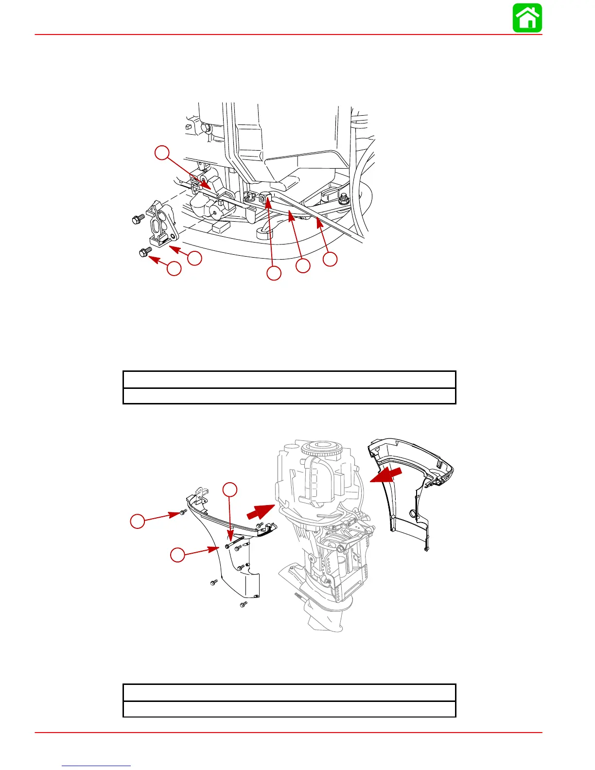
21. Attach swivel linkage to shift rod. Attach swivel/rod assembly to shift link. Make sure
threads are fully engaged but do not tighten completely.
22. Secure bracket and shift rod assembly to side of powerhead with bolts. Torque bolts to
specified torque.
56250
a
b
c
d
e
f
a-Bolts, M6x16-(2)
b-Bracket Assembly
c-Shift Rod Assembly
d-Swivel Linkage
e-Shift Link
f-Shift Rod
Shift Rod Assembly Bolt Torque
75 lb-in. (8.5 Nm)
23. Install lower cowl.
c
a
b
56251
a-Screws (6)-M6x30
b-Lower Cowl
c-Screw-M6x20
Bottom Cowl Bolt Torque
60 lb-in. (7 Nm)

Table of Contents

Other manuals for Mercury 40

Related product manuals