IMPORTANT: Position the Plastigauge on the crankshaft journal so that it will be centered as it lays across the bearing
shell.
4. Place a piece of gauging plastic parallel to the crankshaft on the middle of the open crankshaft connecting rod journal
surface as shown. Install the gauging plastic the full width of the journal.
Plastigauge placement
5. Install the bearing cap.
6. Tighten the bearing cap screws in two steps to the specified torque.
Description
Nm lb‑in. lb‑ft
Bearing cap screws
First torque
25 – 18.4
Final torque
+90°
IMPORTANT: Do not rotate the crankshaft while the gauging plastic is between the bearing and journal.
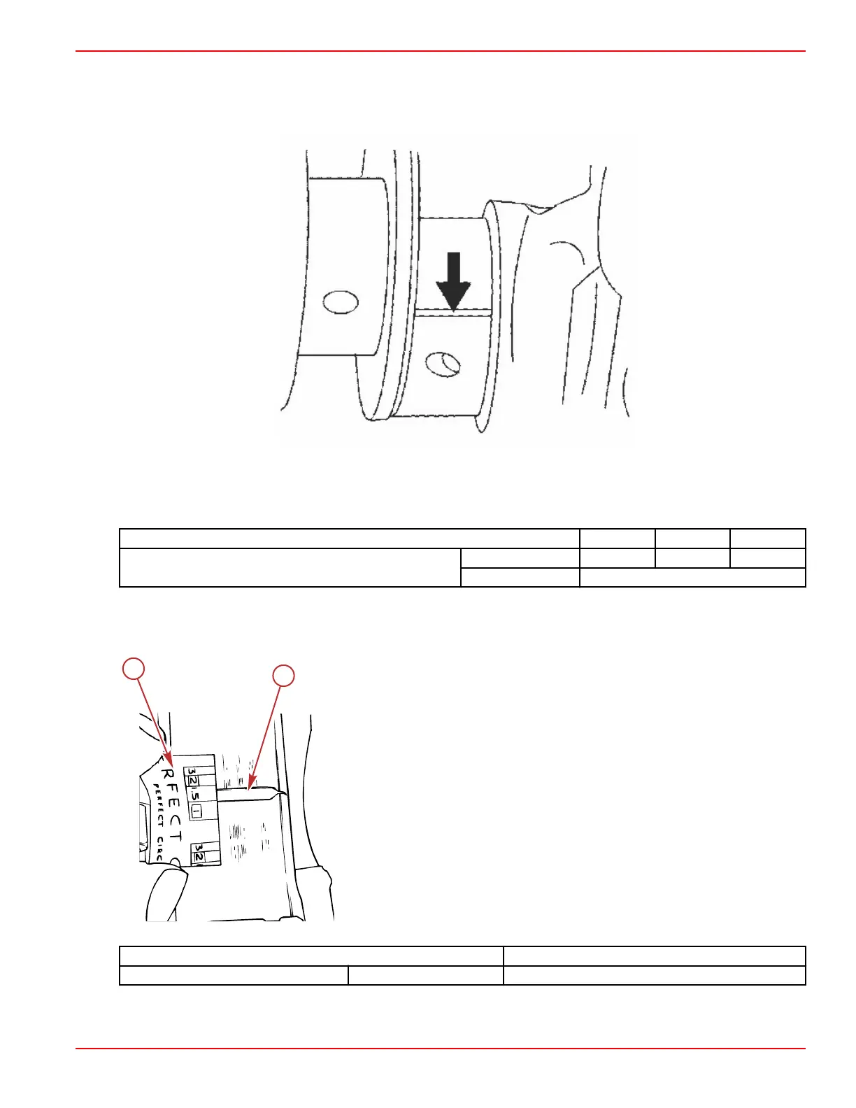
7. Without rotating the crankshaft, remove the bearing cap and use the scale on the gauging plastic envelope to measure the
Plastigauge width at the widest point.
a - Compressed gauging
b - Scale
Description 6.2 Liter (377 cid)
Journal clearance Production 0.047–0.110 mm (0.0019–0.0043 in.)
8. If the clearance is not within specifications, select a new, correct size bearing and recheck the clearance.
Engine Inspection and Assembly
90-8M0099748 eng DECEMBER 2015 © 2016 Mercury Marine Page 3B-31

 Loading...


