3. The level should be between the "COLD" mark and the bottom of the dipstick.
a - Warm range
b - Cold range
4. If the level is below the bottom of the dipstick, but fluid is still visible in the pump reservoir, add the required amount of
specified fluid through the fill cap opening to bring the level up to the "COLD" mark on the dipstick. Do not overfill.
5. If fluid is not visible in the reservoir, a leak exists in the power‑assisted steering system. Find the cause and correct it.
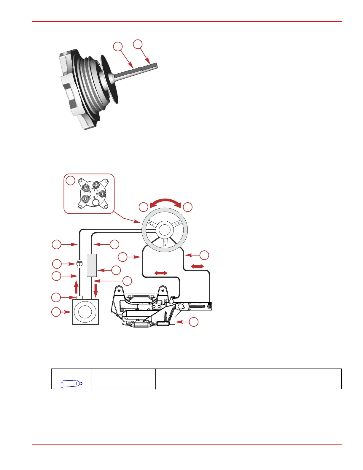
Steering Circuit Component Diagram
a - High‑pressure hose ‑ helm connection "P" to
union fitting 892527
b - Return to cooler hose ‑ helm connection "T"
c - Hose to steering cylinder ‑ helm connection
"L"
d - Hose to steering cylinder ‑ helm connection
"R"
e - Cooler to pump reservoir hose
f - Oil cooler
g - Union fitting 892527
h - High‑pressure hose 8M2018435 ‑ power
steering pump to union fitting 892527
i - Orifice fitting (included in kit)
j - Power steering pump/reservoir
k - Steering cylinder
l - Port steering wheel direction
m - Starboard steering wheel direction
n - Helm connections
NOTE: Arrow denotes oil flow direction.
Connecting the Clevis
1. Lubricate the clevis pin and clevis using 2‑4‑C with PTFE.
Tube Ref No.
Description Where Used Part No.
95
2-4-C with PTFE Clevis pin and clevis 92-802859A 1
2. Connect the clevis to the steering lever. Spread both ends of the cotter pin.
Compact Hydraulic Steering
90-8M0099748 eng DECEMBER 2015 © 2016 Mercury Marine Page 8B-7

 Loading...


