2. On models with a holding strap: install the holding strap and nuts. Tighten the nuts evenly and securely.
3. On models with a mounting ring: install the mounting ring. Tighten the mounting ring securely. Do not overtighten.
4. Connect the other wires to the gauge as appropriate.
5. Install the gauge light socket.
6. Coat all exposed terminals with liquid neoprene.
Tube Ref No. Description Where Used Part No.
25
Liquid Neoprene Electrical terminals and connections 92- 25711 3
7. Reconnect the battery cables to the battery.
Analog Gauge Testing
Oil Pressure, Fuel Level, and Coolant Temperature Gauges
IMPORTANT: A defective gauge must be replaced. Repair is not available.
1. Turn the ignition switch (key switch) to the "OFF" or "0" position, whichever applies to the switch.
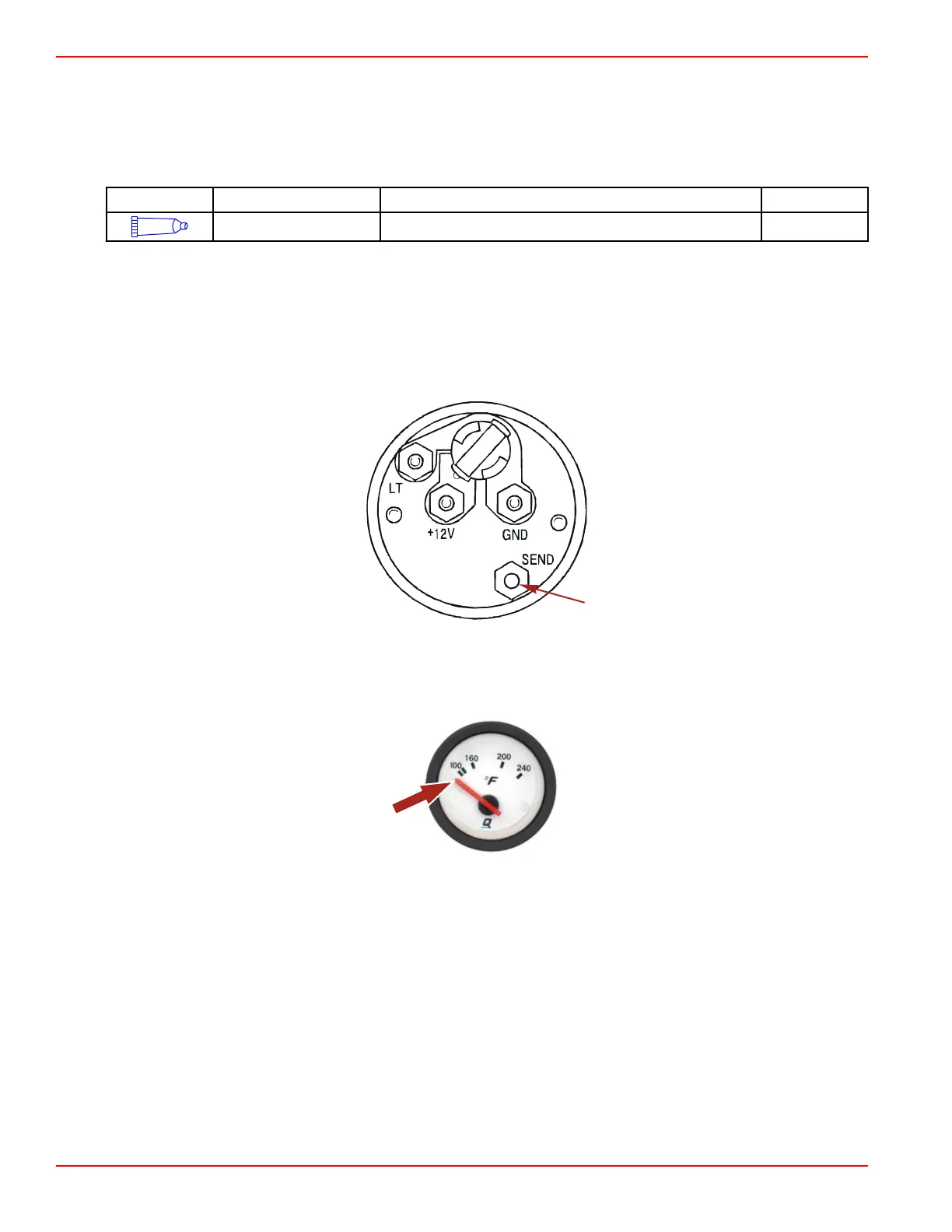
2. Remove the signal wire from terminal SEND ("S") or "G" (gauge), whichever applies to the gauge.
SEND ("S") terminal
3. Turn the ignition switch to the "RUN" or "1" position, whichever applies to the key switch style. The needle of the gauge
must be in the indicated position.
Typical gauge
4. Turn the ignition switch to the "OFF" or "0" position, whichever applies to the key switch.
Instrumentation and Controls
Page 4D-4 © 2016 Mercury Marine 90-8M0099748 eng DECEMBER 2015

 Loading...


