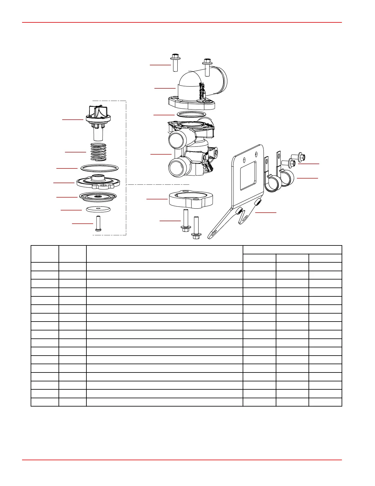
Poppet Valve
Poppet Valve Assembly—Exploded View
1
2
3
4
5
6
7
8
9
10
11
12
13
14
15
16
56674
Ref. No. Qty. Description
Torque
Nm lb‑in. lb‑ft
– 1 Poppet valve subassembly
1 1 Pan head screw 2.5 22.1 –
2 1 Washer
3 1 Diaphragm
4 1 Relief valve plate
5 1 O‑ring
6 1 Compression spring
7 1 Poppet
8 2 M6 x 18 hex head flange screw 8.5 75.2 –
9 1 Inlet fitting
10 1 O‑ring
11 1 Poppet valve housing
12 1 Cover
13 2 M6 x 25 hex head flange screw 8.5 75.2 –
14 1 Poppet valve bracket
15 2 J‑clip
16 2 M6 x 12 hex head flange screw 8.5 75.2 –
Poppet Valve Operation
A poppet valve is installed in the seawater portion of the cooling system of all emission controlled engines in order to control the
flow of the cooling seawater. There are two major functions of the poppet valve.
1. The poppet valve controls the amount of seawater supplied to the exhaust system from idle to wide‑open throttle.
All Models
Page 6A-14 © 2016 Mercury Marine 90-8M0099748 eng DECEMBER 2015

 Loading...


