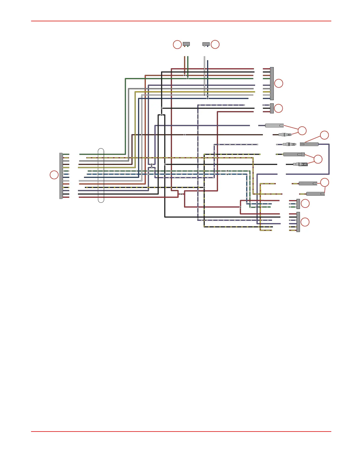
Diagram
1 - 14‑pin Deutsch connector
2 - Key switch connector
3 - Trim switch (outboard only control)
4 - Neutral switch
5 - Lanyard switch (MerCruiser control) or key switch + connection
6 - Lanyard (outboard control) or E‑stop connection
7 - Warning horn
8 - Accessory relay connection (15 amp)
9 - Gauge connector
10 - CAN P (CAN 1) with resistor cap
11 - CAN V (CAN 3) with weather cap
NOTE: Dual engines are treated as two singles in the same boat and are not connected together.
NOTE: The lanyard stop switch on MerCruiser control (purple and purple/white wires) breaks power to the ECM or ignition to
stop the engine. The switch is normally
closed
until activated. Therefore the purple and purple/white wires must be connected
together if lanyard stop switch is not used, or if the E‑stop switch is used.
NOTE: Outboard control E‑stop switch (black and black/yellow wires) connects ground to ECM to stop engine. The switch is
normally
open
; the circuit closes when the switch is activated. Wires must be separate unless connected through E‑stop
switch.
Up to 15 amps total accessory power can be provided; on purple wire (switched) and the red wire (continuous power).
An accessory relay kit can be used for loads up to 40 amps. Refer to the MerCruiser Parts and Accessory Guide or
MerCruiser Rigging Guide.
1
A B C D E F G H J K
L M
N P
A B C D E F G H J K
A B C
A B C D E F
A B C
1
1
1
1
1
A B
A B
1
1
1
2
3
5
8
9
10
11
4
6
7
12339
GRN
WHT
DK BLU
DK BLU
PPL/WHT
PPL/WHT
BLK/YEL
YEL/RED
YEL/RED
BLK/YEL
PPL
BLK
RED
RED
GRN/WHT
BLU/WHT
PPL/WHT
YEL/RED
GRN
GRA
BRN
YEL
GRN/WHT
BLU/WHT
DK BLU
WHT
ORN
BLK/YEL
PPL
BLK
RED
WHT
YEL
GRA
BRN
PPL
PPL
PPL
GRN
ORN
BLK
BLK
BLK
RED
RED
ORN
YEL/RED
Instrumentation and Controls
90-8M0099748 eng DECEMBER 2015 © 2016 Mercury Marine Page 4D-21

 Loading...


