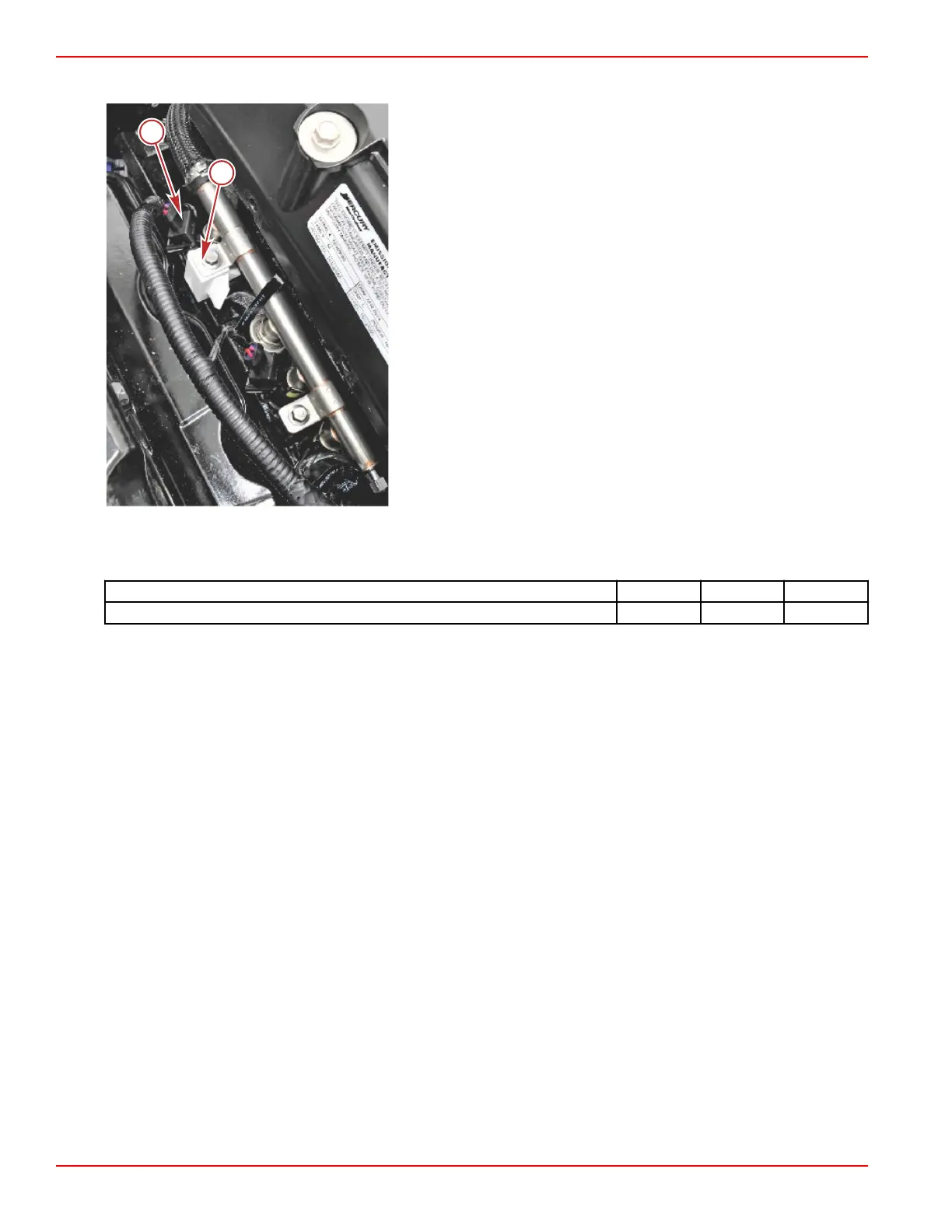
3. On DTS engines install a spacer on the #6 injector to control the clocking on the injector.
a - #6 injector
b - Spacer
4. Install the fuel rail, ensuring that all injectors seat correctly.
5. Install the fuel rail retaining screws and tighten them to the specified torque.
Description
Nm lb‑in. lb‑ft
Fuel rail retaining screws 12.2 108 –
6. Connect the fuel supply line to the fuel rail.
7. Connect the injectors to the engine harness.
8. Install the flame arrestor. Tighten the nut securely.
9. Install the PCM relay bracket as listed.
a. Connect the MAP sensor.
b. Install the 14‑pin data harness connector and retaining nut.
c. Install the depth/RS‑485 and the boat harness (tanks) connectors.
d. Install the circuit breaker.
e. Install the fuses, 10‑pin diagnostics connector, and the J1939 diagnostic connection.
f. Attach the wire harness to the PCM relay bracket with three cable ties.
g. Install the clean power connection and OBD‑M MIL light connector.
h. Install the remaining relays and the transom harness connector.
i. Install the alternator sense connector, port side post O2 sensor connector and relays.
j. Install the oil fill tube.
k. Install the starboard injector connectors.
l. Connect the three PCM connectors.
m. Install the four mounting screws, holding the PCM relay bracket to manifold.
n. Connect the neutral switch connector, and the demand sensor harness.
10. Install the engine cover.
11. Connect the battery, installing the positive (+) battery lead first.
MPI ECT Fuel System
Page 5A-28 © 2016 Mercury Marine 90-8M0099748 eng DECEMBER 2015

 Loading...


