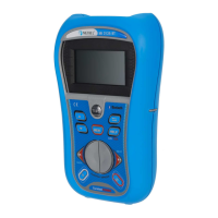
MI 3102(H) BT EurotestXE Measurements
71
5.15 PE conductor resistance
In TN system instrument measures the resistance of the protection conductor from the power
transformer to the measurement site.
In TT system the resistance of protection conductor from mains outlet to earth electrode and
back to the power transformer via soil and the transformers earthling system is measured.
See chapter 4.2 Function selection for instructions
on key functionality.
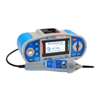
Figure 5.60: PE conductor resistance
Test parameters for PE conductor resistance measurement
Selection of PE conductor resistance sub-function [Rpe,Rpe(rcd)]
Maximum resistance [OFF, 0.1 ÷ 20.0 ].
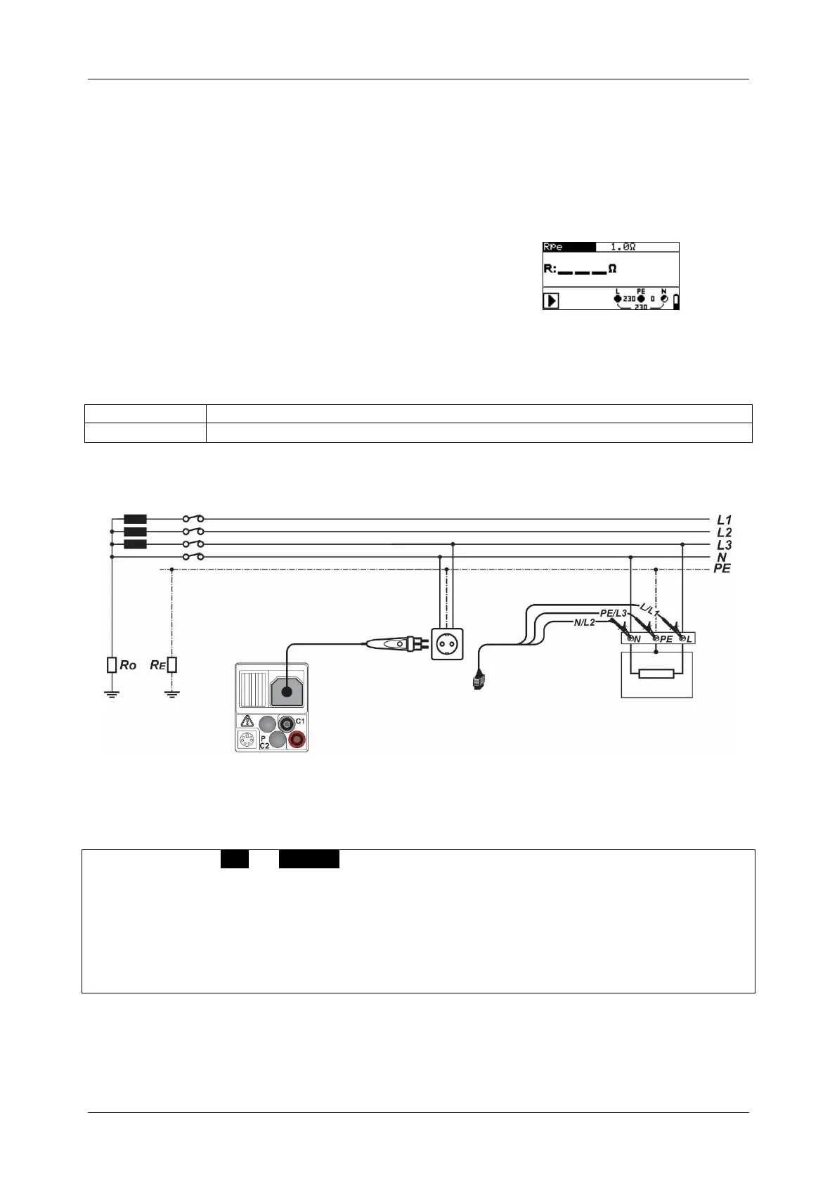
Circuits for measurement of PE conductor resistance
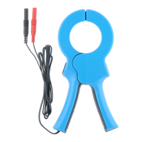
Figure 5.61: Connection of plug commander and 3-wire test lead
PE conductor resistance measurement procedure
Select the Rpe or Rpe(rcd) sub-function using the function selector keys and UP /
DOWN keys.
Select test parameters (optional).
Connect test cable to the instrument.
Connect test leads to the item to be tested (see
Figure 5.61).
Press the TEST key to perform the measurement.
Store the result by pressing the MEM key (optional).
 Loading...