SECTION II
TESTING AND TROUBLESHOOTING
© Midmark Corporation 2002 SF-1803 Page 2-19 Printed in U.S.A.
Code C671. (Continued)
(Error Type: FATAL )
(Continued)
C671: SELECT MODE
PRESSURE OVERLIM
UNPLUG / RE-PLUG UNIT
Gauge pressure inside
chamber is greater than
34.8 PSIg (240 kPa) during
SELECT mode.
Pressure Transducer or
Main P.C. Board Malfunc-
tioning.
Check for 5.0 VDC
between TP2 & TP4 &
pins of Pressure Trans-
ducer. (Refer to Sche-
matic in Section 5).
Voltage should be apprx.
4.5 VDC at all times with
unit plugged in. Also, run
Service Diagnostics.
If voltage is not present or Ser-
vice Diagnostics reveals a
problem replace P.C. Board
(Refer to para 4.13).
Code
C672.
(Error Type: FATAL )
C672: FILL MODE
PRESSURE OVERLIM
ITEMS NOT STERILE
UNPLUG / RE-PLUG UNIT
Gauge pressure inside
chamber is greater than
34.8 PSIg (240 kPa) during
FILL mode.
Air Valve malfunctioning. Check operation of Air
Valve by running Service
Diagnostics and check
coil resistance. Refer to
Schematic of Main P.C.
Board.
Replace Air Valve Assembly
(Refer to para 4.15).
Pressure Transducer or
Main P.C. Board Mal-
functioning.
Check for 5.0 VDC
between TP2 & TP4 &
pins of Pressure Trans-
ducer. (Refer to Sche-
matic in Section 5).
Voltage should be apprx.
4.5 VDC at all times with
unit plugged in. Also, run
Service Diagnostics.
If voltage is not present or Ser-
vice Diagnostics reveals a
problem replace P.C. Board
(Refer to para 4.13).
Code
C673 HEATUP
Code C674 STERILIZE
(Error Type: FATAL )
(Refer to column on left for
codes and description)
C67X: XXXXXX MODE
PRESSURE OVERLIM
ITEMS NOT STERILE
UNPLUG / RE-PLUG UNIT
Gauge pressure inside
chamber is greater than
34.8 PSIG (240 kPa) dur-
ing specific mode.
Air Valve malfunctioning. Check operation of Air
Valve by running Service
Diagnostics and check
coil resistance. Refer to
Schematic of Main P.C.
Board.
Replace Air Valve Assembly
(Refer to para 4.15).
Steam Temperature Sen-
sor (RTD), located in rear
of chamber, malfunction-
ing.
Remove plug connector
at J12 on P.C. Board and
check resistance value
(ohms) of RTD between
white and red leads.
Resistance values
should be between the
following:
75°F (23°C) = 1090
ohms.
545°F (285°C) = 2066
ohms.
Above values +/- 10
Ohms
If Steam Temperature probe
shows open or values outside
resistance ranges replace
probe (Refer to para 4.10).
Pressure Transducer or
Main P.C. Board Mal-
functioning.
Check for 5.0 VDC
between TP2 & TP4 &
pins of Pressure Trans-
ducer. (Refer to Sche-
matic in Section 5).
Voltage should be apprx.
4.5 VDC at all times with
unit plugged in. Also, run
Service Diagnostics.
If voltage is not present or Ser-
vice Diagnostics reveals a
problem replace P.C. Board
(Refer to para 4.13).
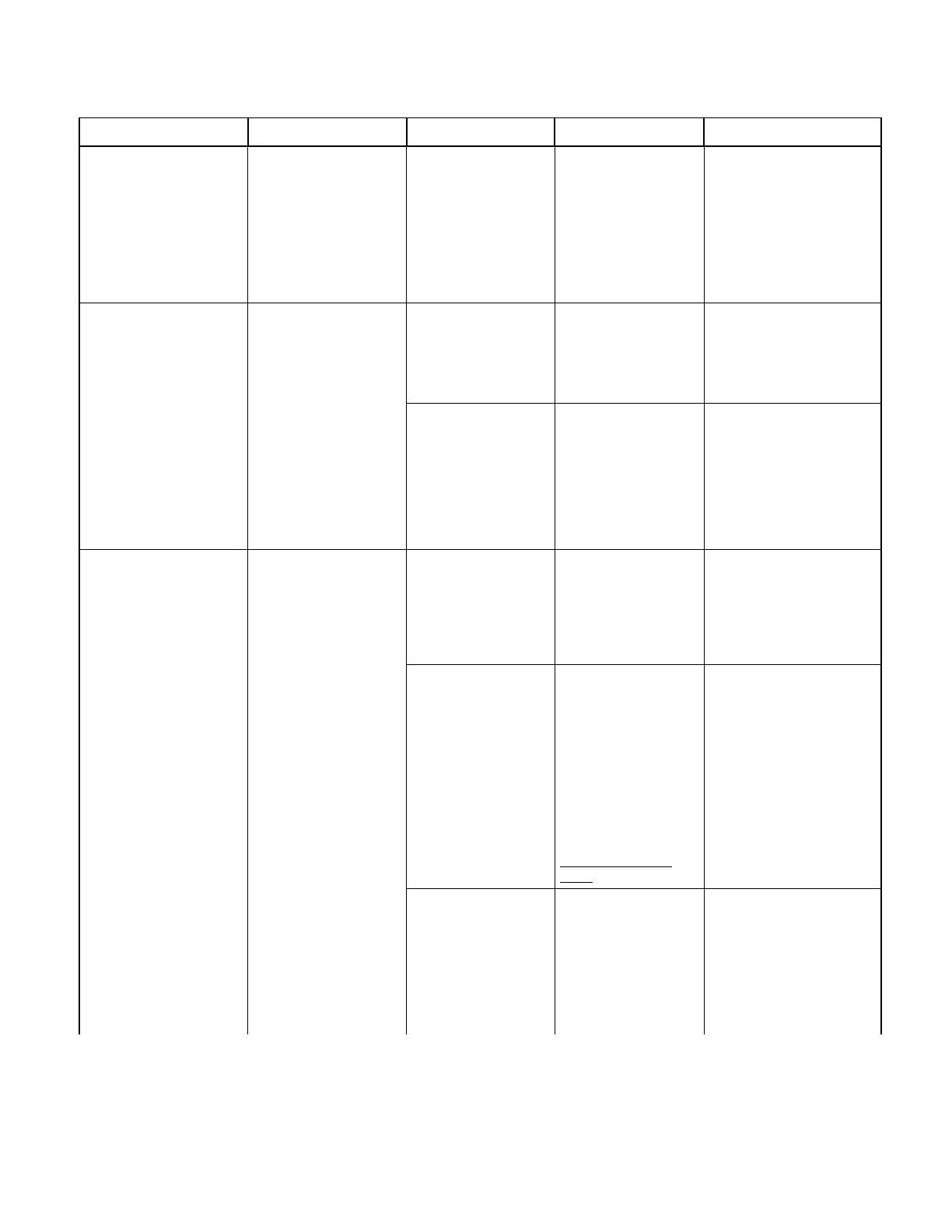
Table 2-3. Troubleshooting Guide
Problem Display / Symptom Probable Cause Check Correction
Return To Table of Contents