OM-253 906 Page 18
SECTION 5 − INSTALLATION
5-1. Serial Number And Rating Label Location
The serial number and rating information for this product is located on the front. Use rating label to determine input power requirements and/or rated
output. For future reference, write serial number in space provided on back cover of this manual.
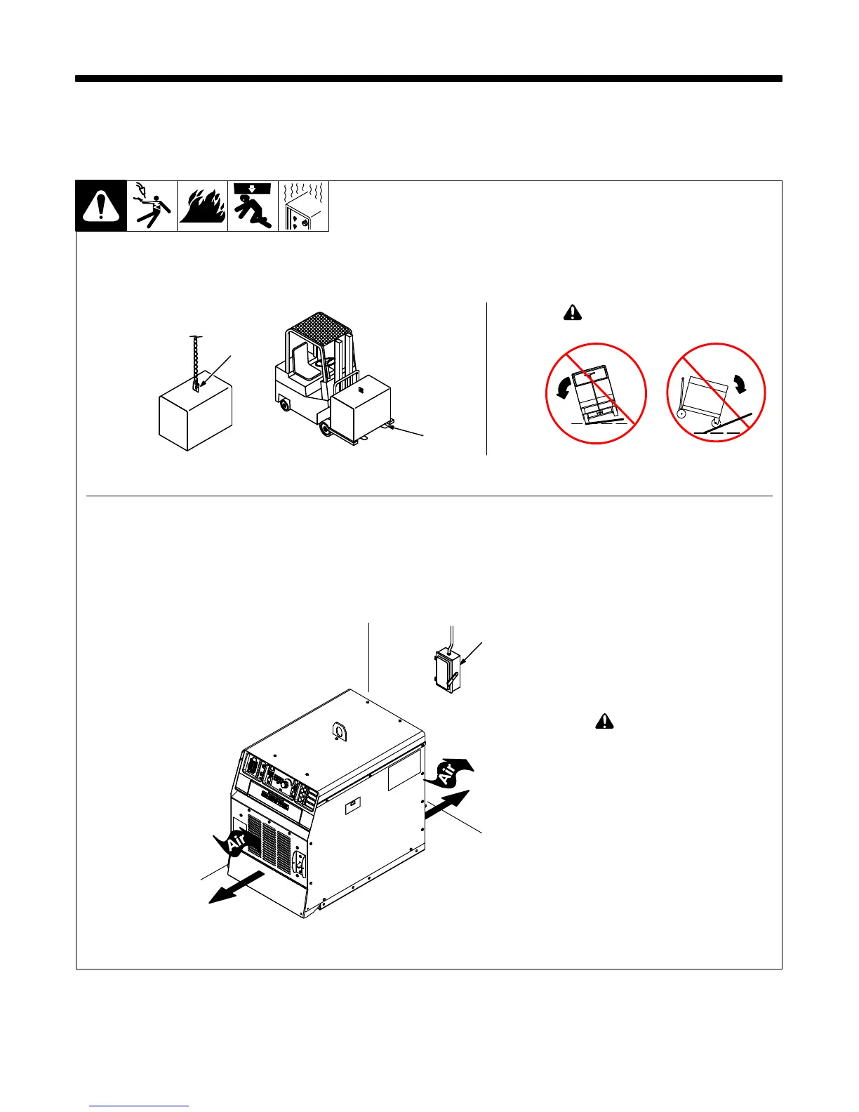
5-2. Selecting a Location
loc_2 3/96 − Ref. 805 142-A
1 Lifting Eye
2 Lifting Forks
Use lifting eye or lifting forks to
move unit.
If using lifting forks, extend forks
beyond opposite side of unit.
3 Line Disconnect Device
Locate unit near correct input
power supply.
! Special installation may be
required where gasoline or
volatile liquids are present −
see NEC Article 511 or CEC
Section 20.
Movement
Location
460 mm
(18 in.)
460 mm
(18 in.)
3
Tipping
! Do not move or operate
unit where it could tip.
OR
1
2
 Loading...