OM-253 906 Page 22
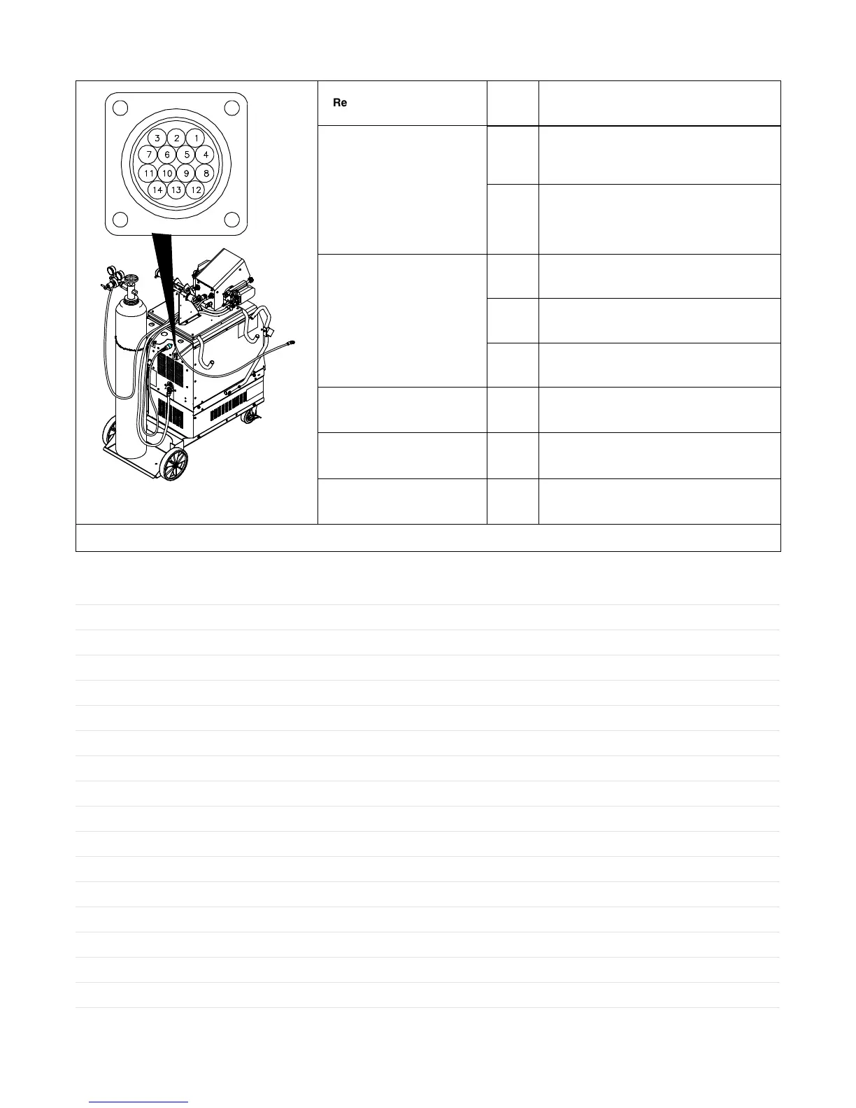
5-6. Remote 14 Wire Feeder Control Receptacle Information
Ref. 805 144-A / Ref. 048 286-B
Remote 14 Feeder Control Socket* Socket Information
24 VOLTS AC
8, 12 24 volts AC. Protected by supplementary
protector CB2.
1,4 24 volts AC return. Connected to chassis
common. Completes 24 volts AC power supply
circuit to feeder.
SERIAL
COMMUNICATION
6 Isolated RS-485 (+) serial communication signal.
3 Isolated RS-485 (−) serial communication signal.
5 Isolated serial communication common.
POSITIVE VOLT SENSE
14 Positive weld output voltage sense signal.
NEGATIVE VOLT SENSE
11 Negative weld output voltage sense signal.
GND
2,10 Chassis common.
*The remaining sockets are not used.
Notes
 Loading...